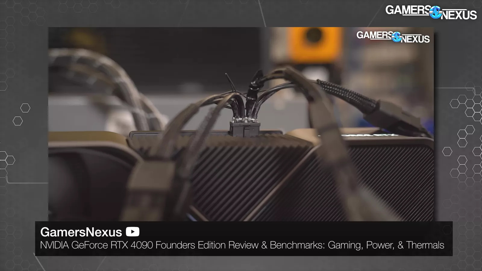
We dig deep into the 12VHPWR and 12V-2x6 specifications, highlighting the contradictory design documents leading to confusion as manufacturers cut corners
The Highlights
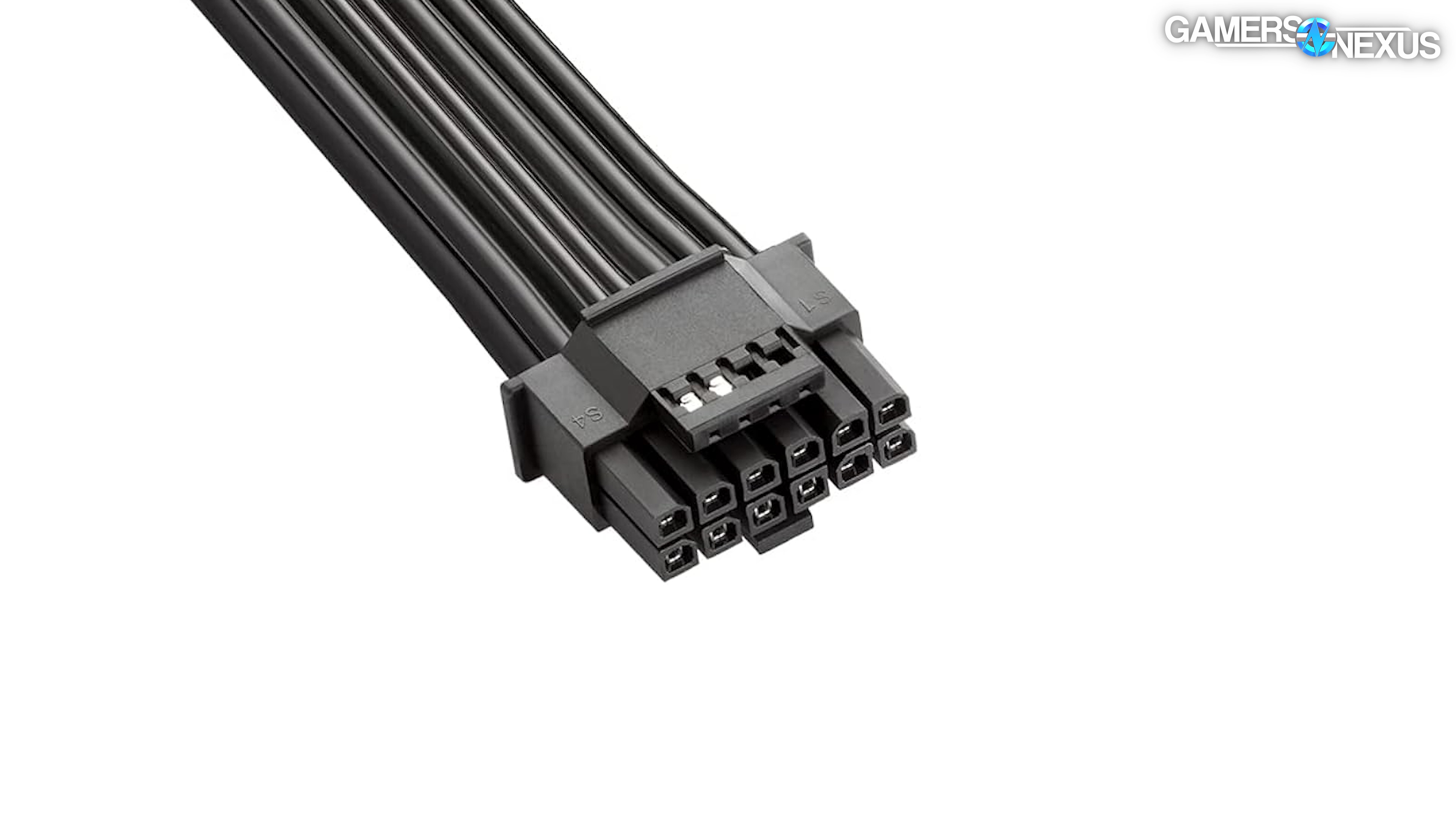
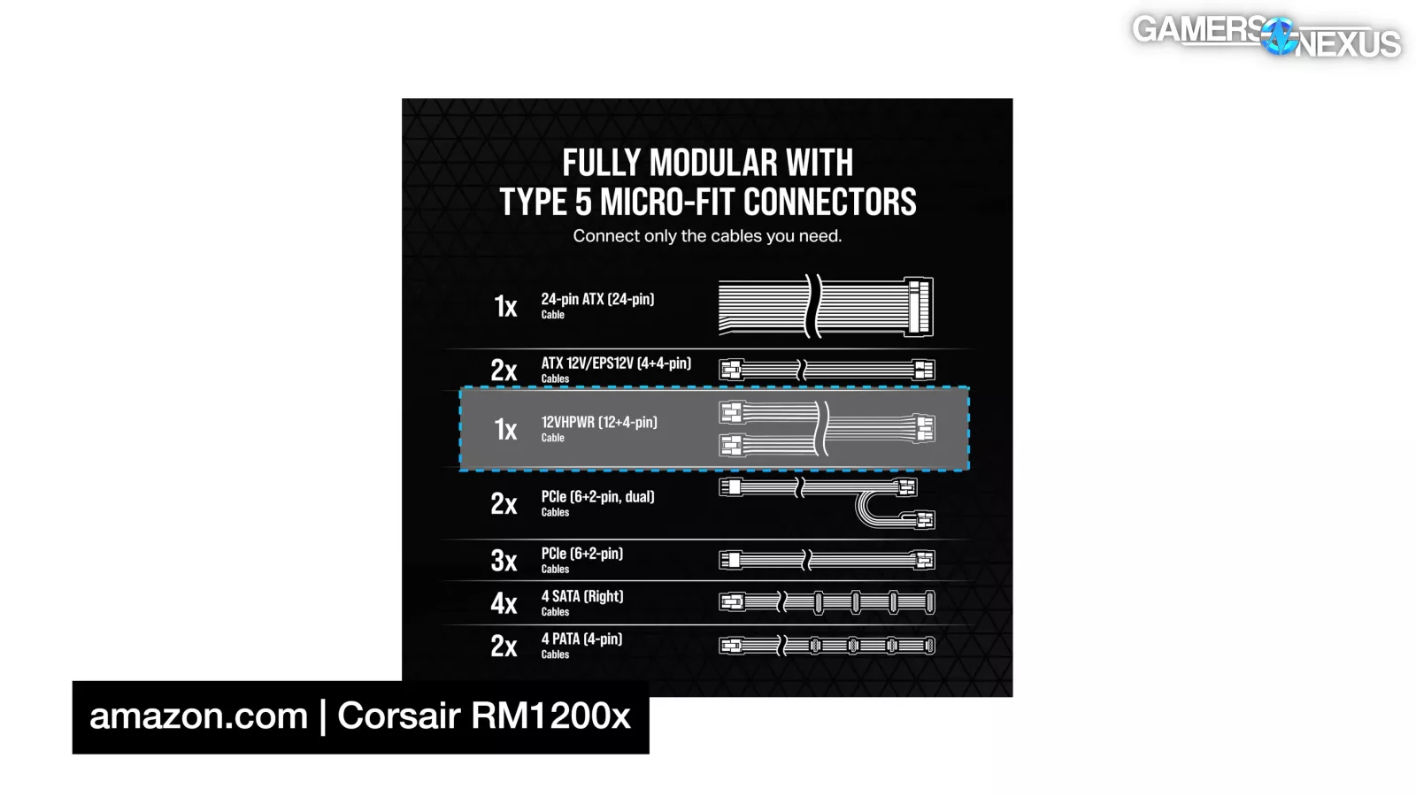
- The 12VHPWR connector was designed to be smaller, reduce cable clutter, and to facilitate more flexibility in PCB design
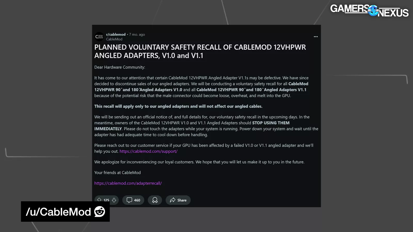
- CableMod created an adapter to mitigate some of the issues facing 12VHPWR but only ended up recalling its product
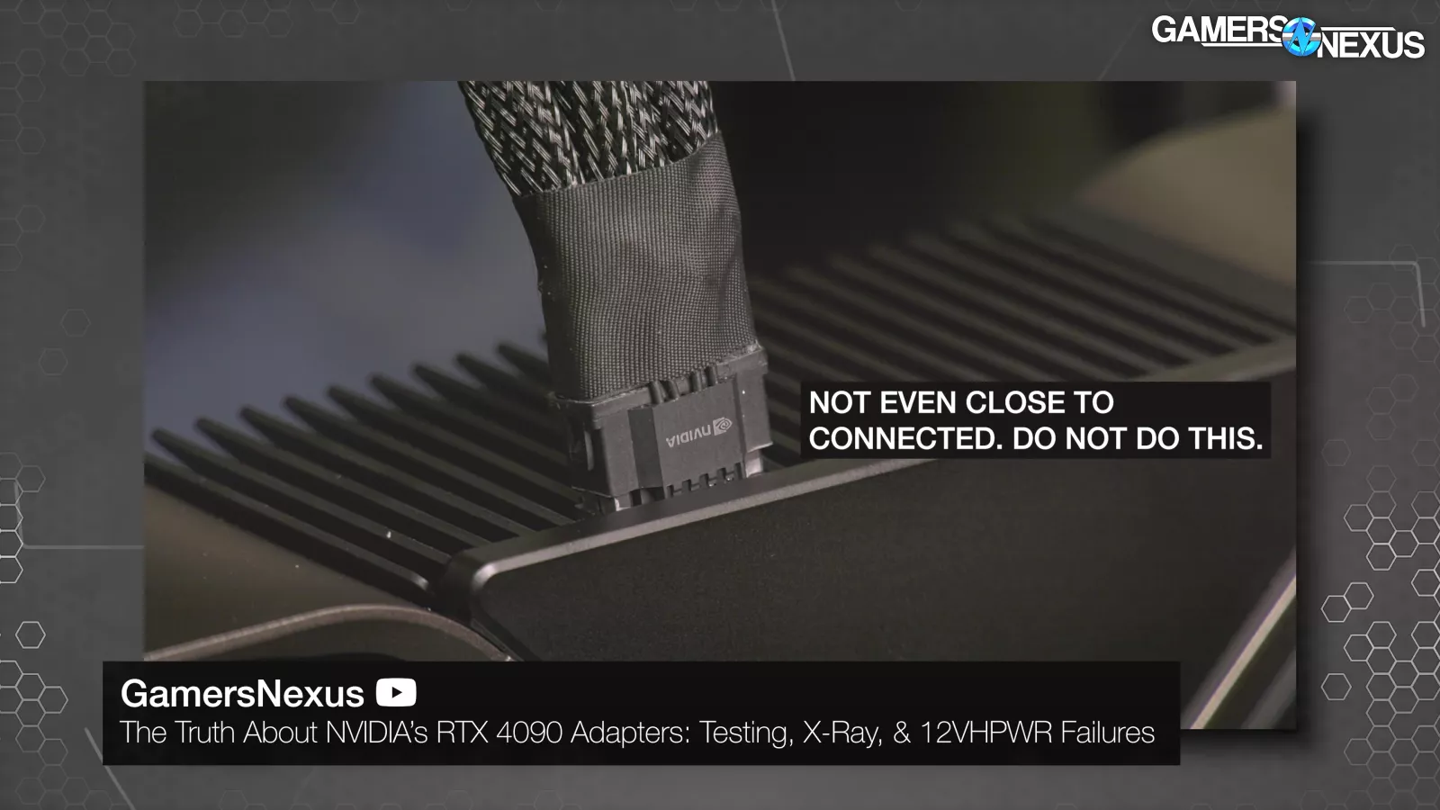
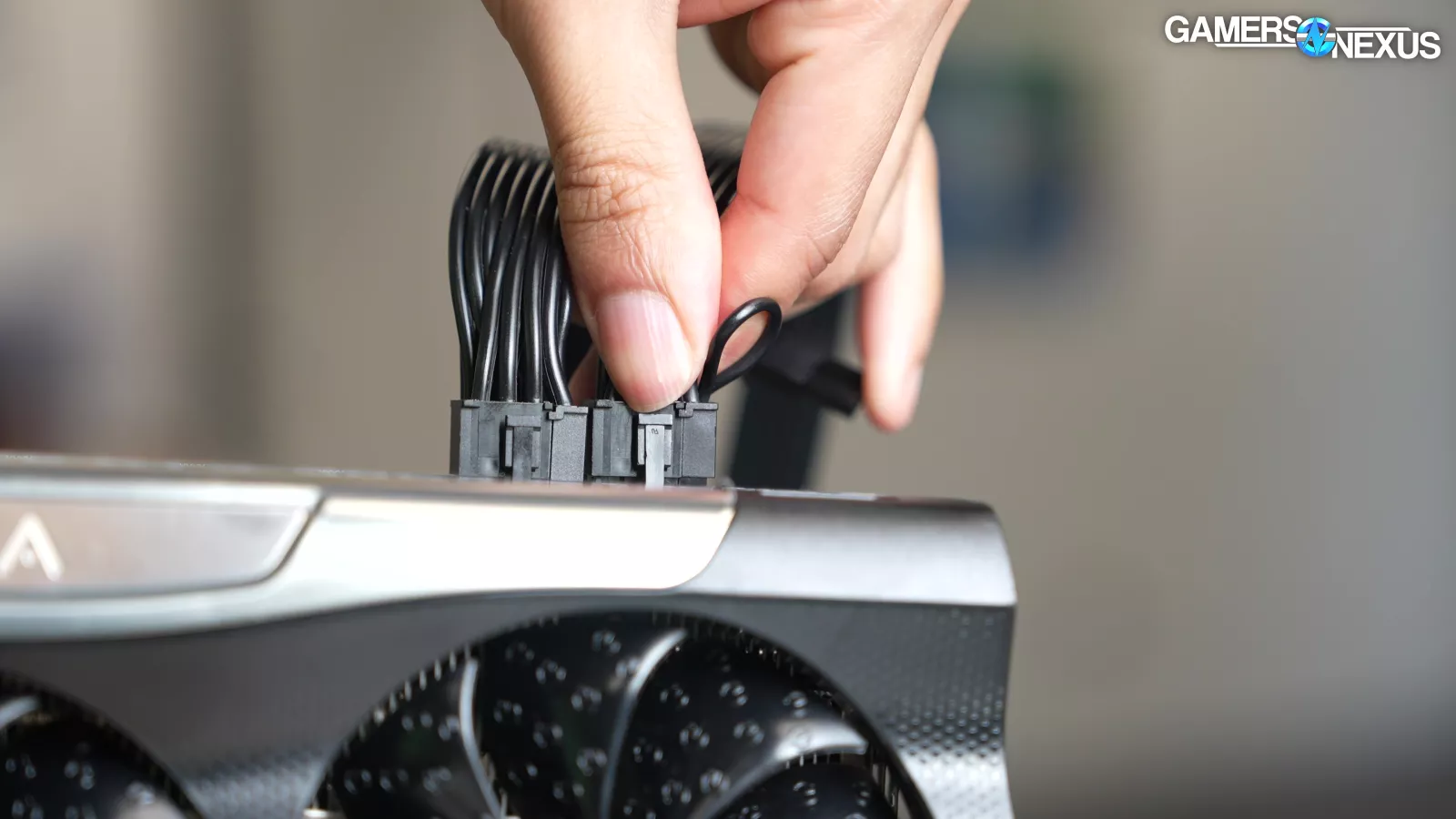
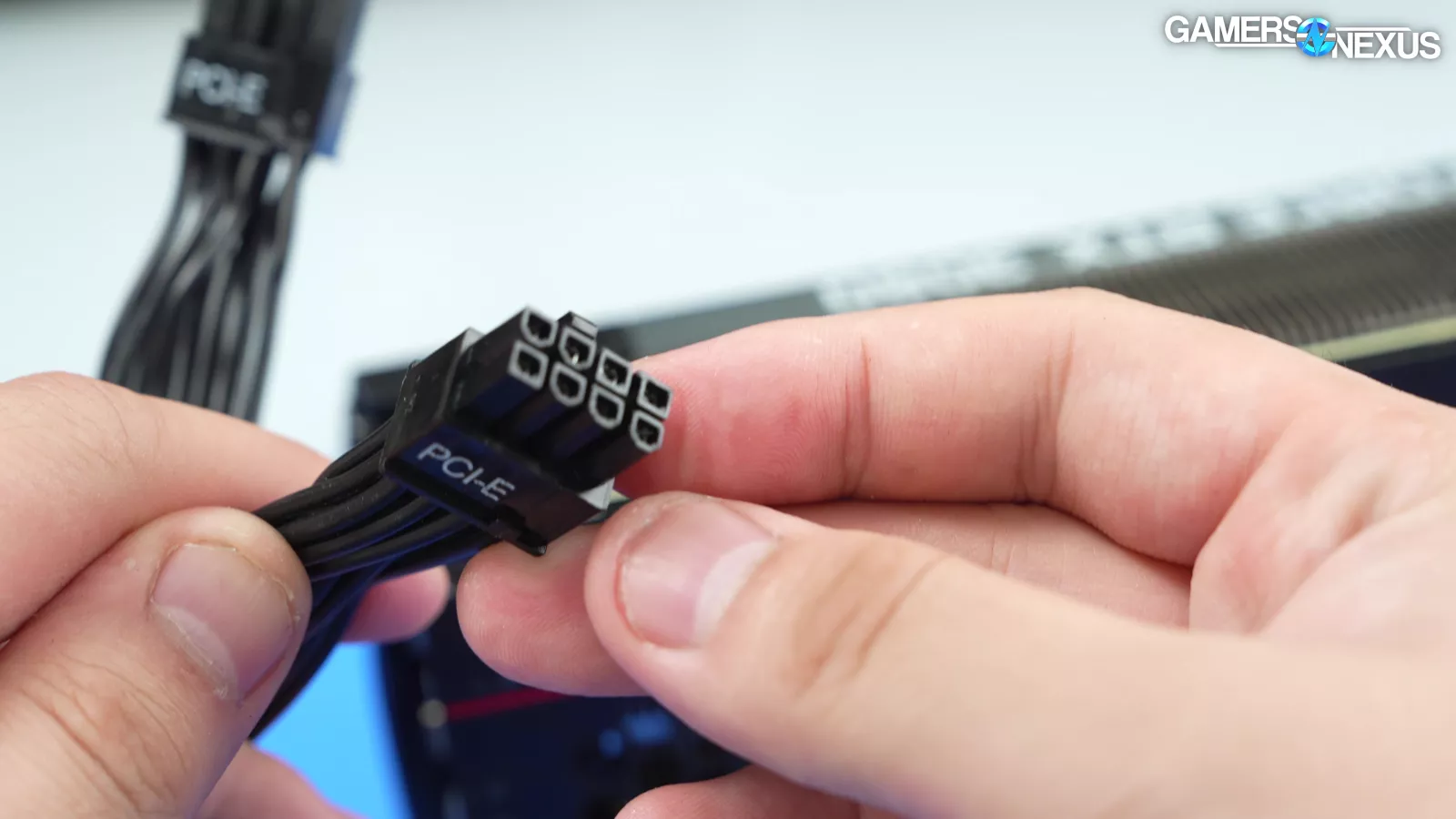
- When using a 12VHPWR cable, it’s important to make sure the cable is fully seated
Table of Contents
- AutoTOC
Intro
12VHPWR doesn't exist anymore -- technically; it's transitioned to 12V-2x6, and NVIDIA has been using it for months, except technically not. 12VHPWR is also different from the 12-pin 30 series connector, but also different from 12V-2x6.
You apparently need a 4-spring connector, or maybe a 3-dimple is fine, or maybe tulips or square plugs are best, or you can do whatever, actually. Design oversights mixed with improper insertion cause an initial wave of problems.
Editor's note: This was originally published on October 7, 2024 as a video. This content has been adapted to written format for this article and is unchanged from the original publication.
Credits
Host, Writing
Steve Burke
Research, Writing
Patrick Lathan
Camera, Video Editing
Vitalii Makhnovets
Camera, Video Editing, Animation
Andrew Coleman
Writing, Web Editing
Jimmy Thang
Accuracy Fact Check & Peer Review
Aris Mpitziopoulos (Cybenetics & HW Busters)
Roman 'Der8auer Hartung (Thermal Grizzly)
'Elmor' (Elmor Labs)
Anonymous Engineers (Formerly at GPU Manfs)
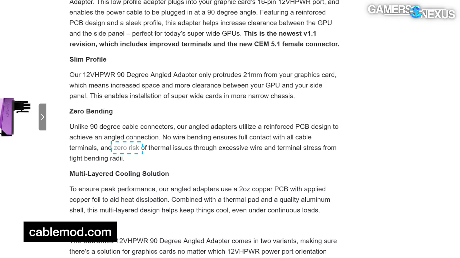
CableMod markets its solutions as superior on the back of this, says there is zero risk, then later royally screwed its own design and issued a recall of all its angled adapters.
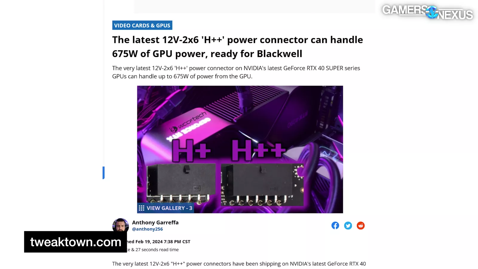
A lot of people got the wrong idea that 12V-2x6 cables are intended to be used at 675 W, but they’re not. Wccftech reported that “PCI-SIG Warns of Potential Overcurrent/Overpower Risk With 12VHPWR Connectors Using Non-ATX 3.0 PSU & Gen 5 Adapter Plugs,” except PCI-SIG mentioned neither Non-ATX 3.0 PSUs nor Gen 5 adapters in that very post.
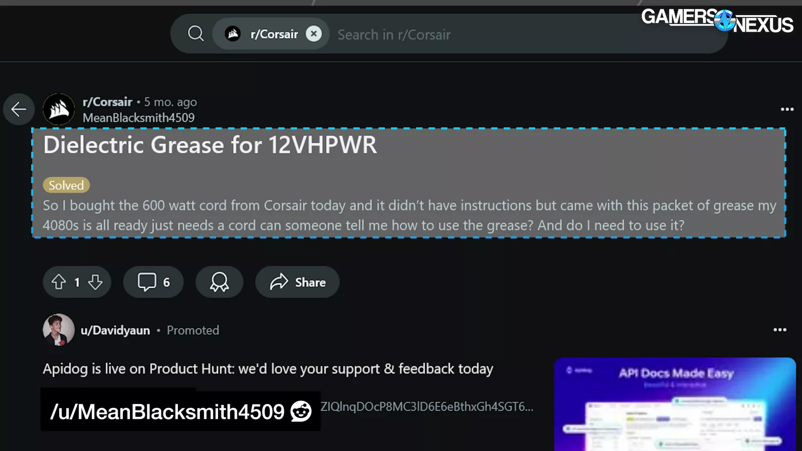
And Corsair... is mailing out plug lube.
12VHPWR is a mess.
Our story here started out as a cut-and-dry failure analysis of the CableMod angled adapters. We paid a third-party failure analysis lab to help us investigate CableMod’s specific failures as a post-mortem since no official cause was ever released, but as we went further, we realized we needed to start from the beginning.
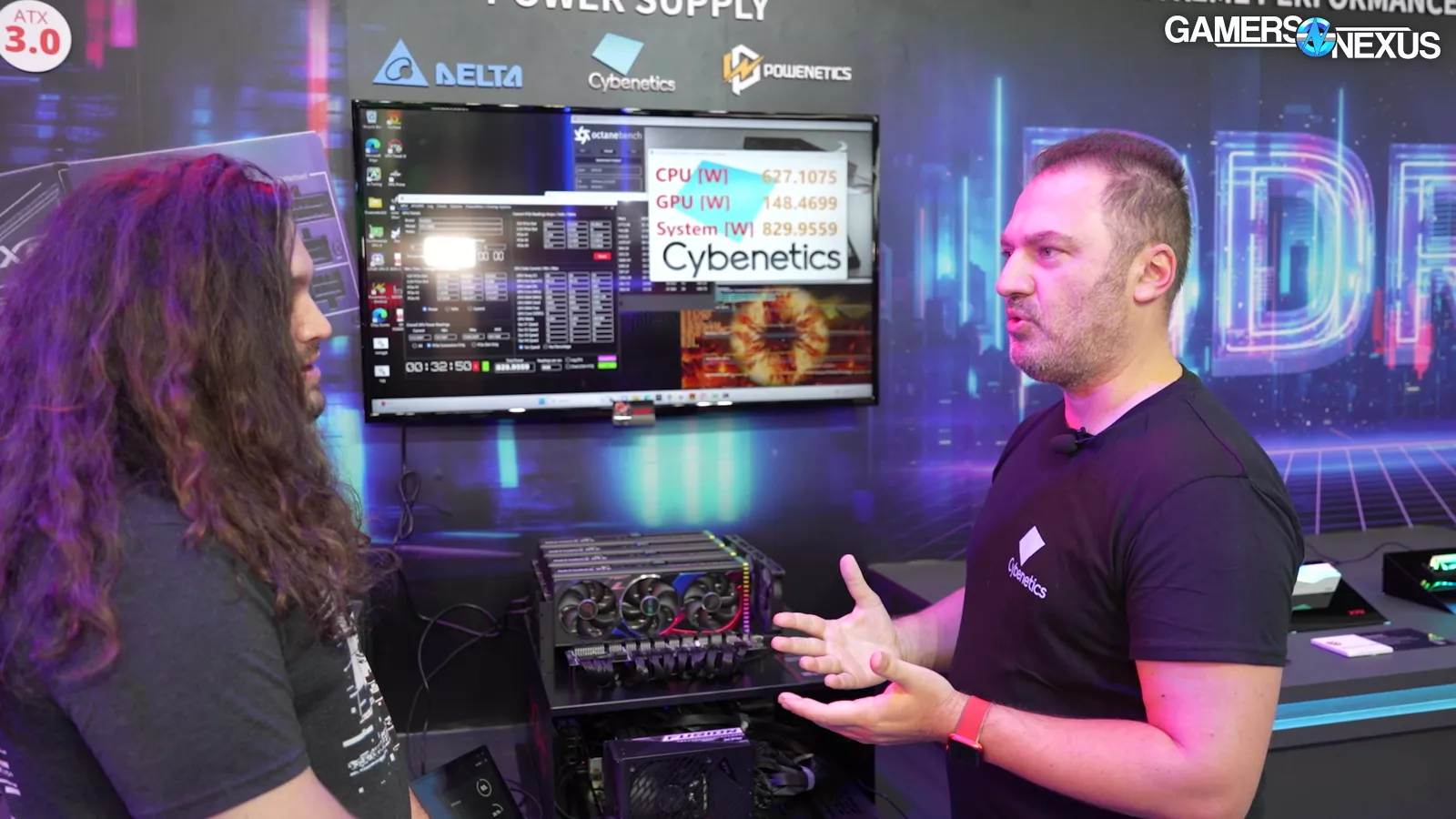
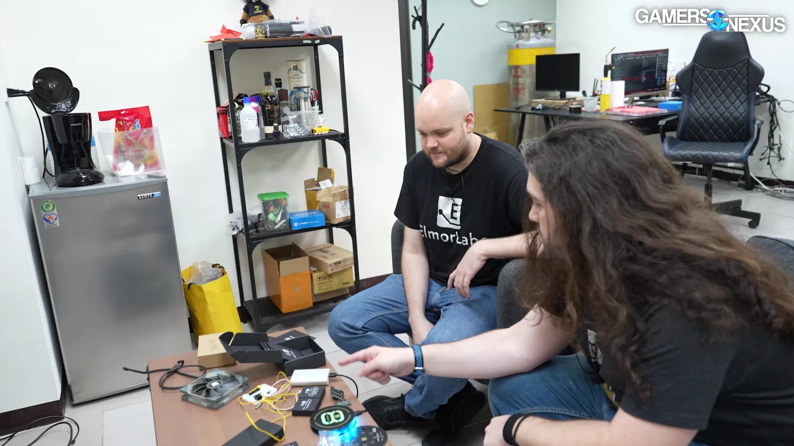
For this story, we did something we’ve been doing more recently, which is we sent our video to a number of peer reviewers and fact checkers to ensure accuracy of our research and statements. That’s because this topic is complex and spans several years of messy developments. These reviewers include Aris Mpitziopoulos, the engineer who runs Cybenetics, (a power supply validation lab that created the modern PSU rating system), Roman Hartung, aka der8auer, who reviewed our video for accuracy of statements (particularly related to engineering and electrical topics). He also runs Thermal Grizzly. Other reviewers include Elmor of ElmorLabs, who’s the brilliant engineer behind some of the most useful testing tools in the industry and a few anonymous engineers in the industry who were formerly involved in dealing with these specifications.
We've all been using 6- and 8-pin PCIe power connectors on GPUs for a couple of decades without major controversy.
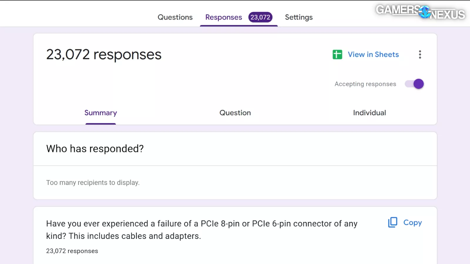
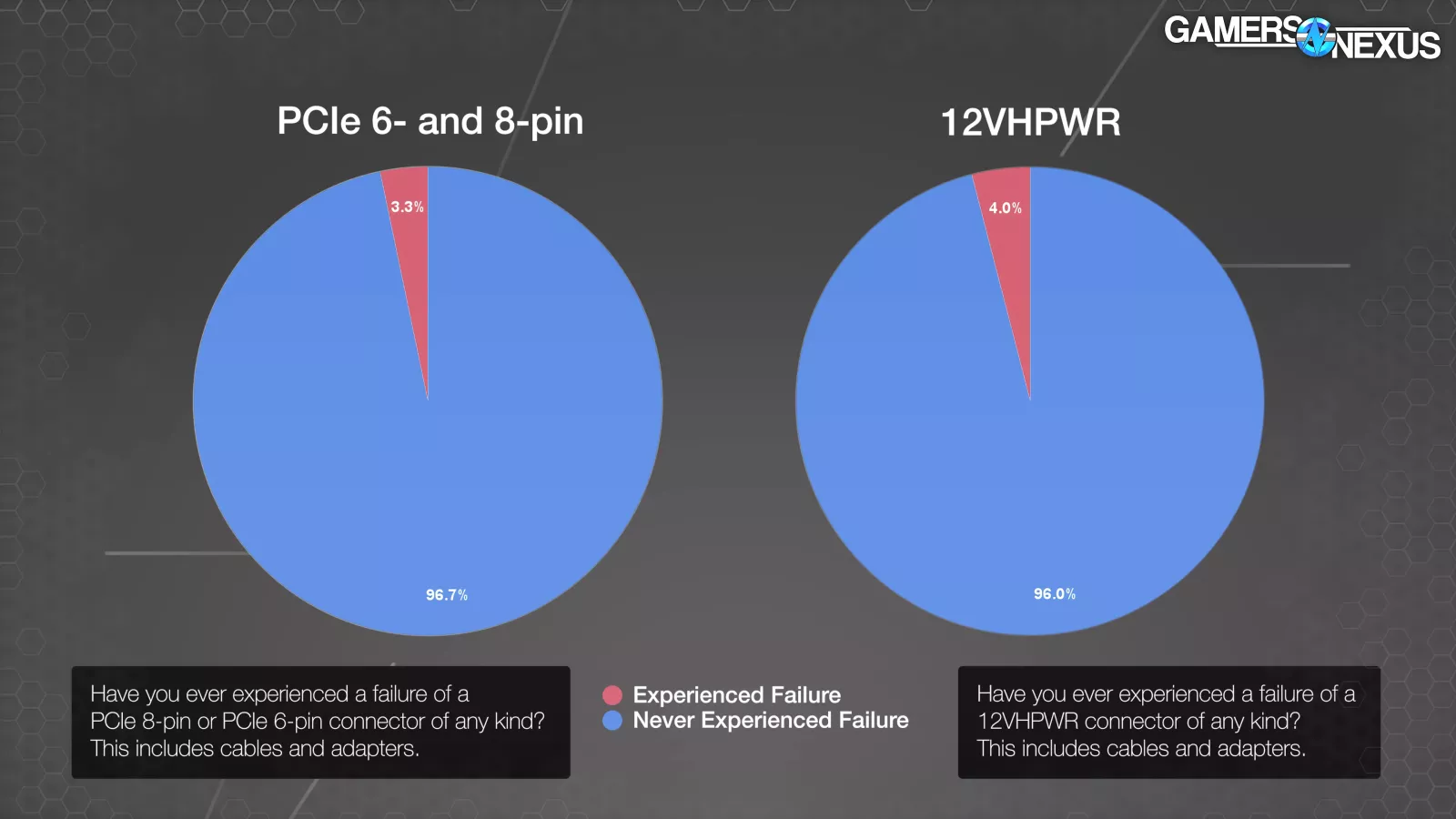
We ran a survey that many of you participated in: out of approximately 23,000 responses, 3.3% of users that had ever used the old PCIe connectors had had a failure, and 4.0% that had ever used a 12VHPWR connector had had a failure.
For purposes of this story, we may colloquially use the term "PCIe connector" to refer to PCI Express 2x4 Auxiliary Power Connector, aka PCIe 6 and 8 pin, although technically, all of the connectors we're discussing today are "PCIe." That’s just to make it a little shorter. There's some sample bias there with all the attention on 12VHPWR, but even assuming some error in here, that’s a similar failure rate over a shorter time span.
A lot of the 12VHPWR reports were of the CableMod adapters, which we already knew were problematic.
With the recent-ish CableMod adapter failures and recall, we're coming back to organize and conclude this story.
First, though, let's look at some CableMod adapters and try to understand what went so wrong that they issued a government-level recall -- something must have been different.
A lot of this content in this article is sort of a historical look back at a massive timeline of the whole saga. We’re going to be stepping through a lot of materials and documents.
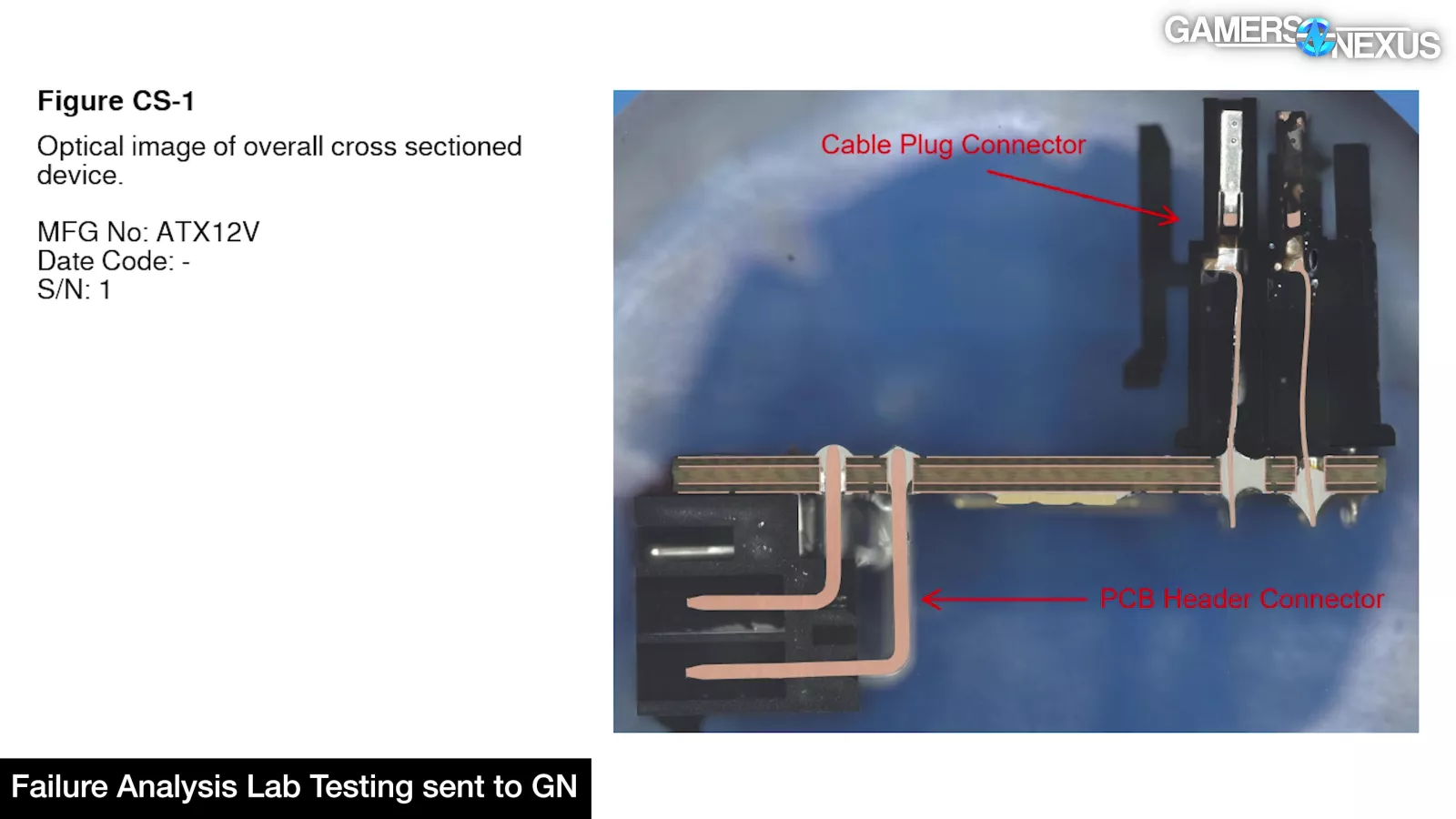
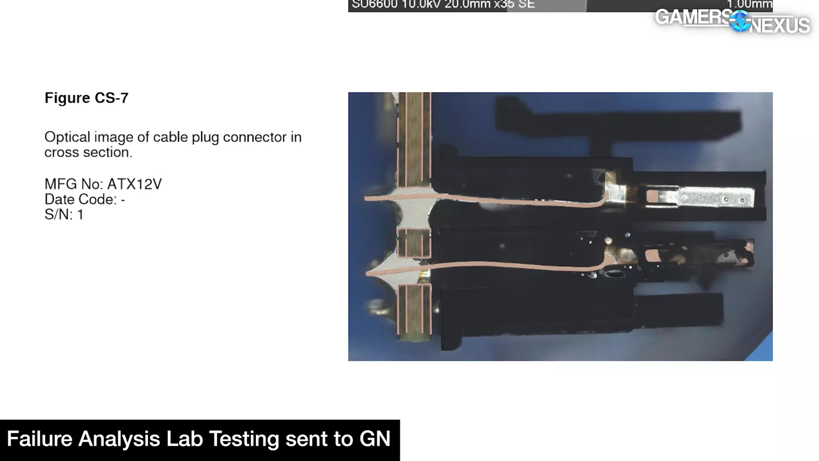
We have some additional failed cards and connectors from CableMod so credit to them for at least being involved in the investigation, but ultimately, we found three that were really representative or otherwise good samples and sent those in. We did a cross-section on one of them and we've got some pretty interesting stuff.
Part 1: Failure Analysis
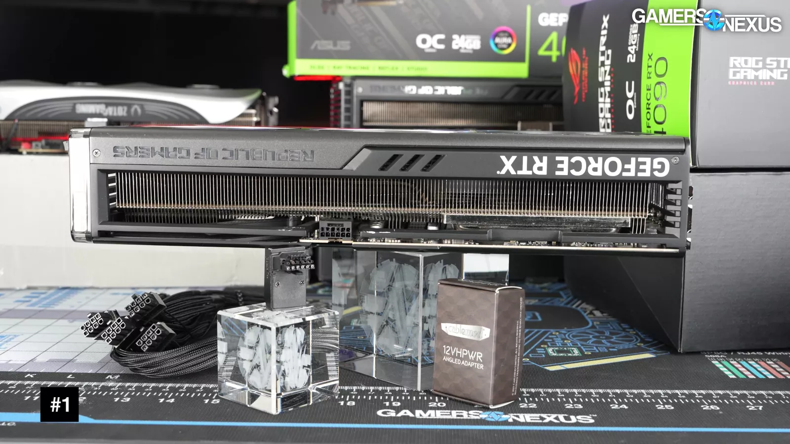
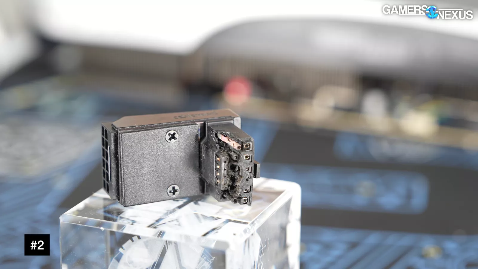
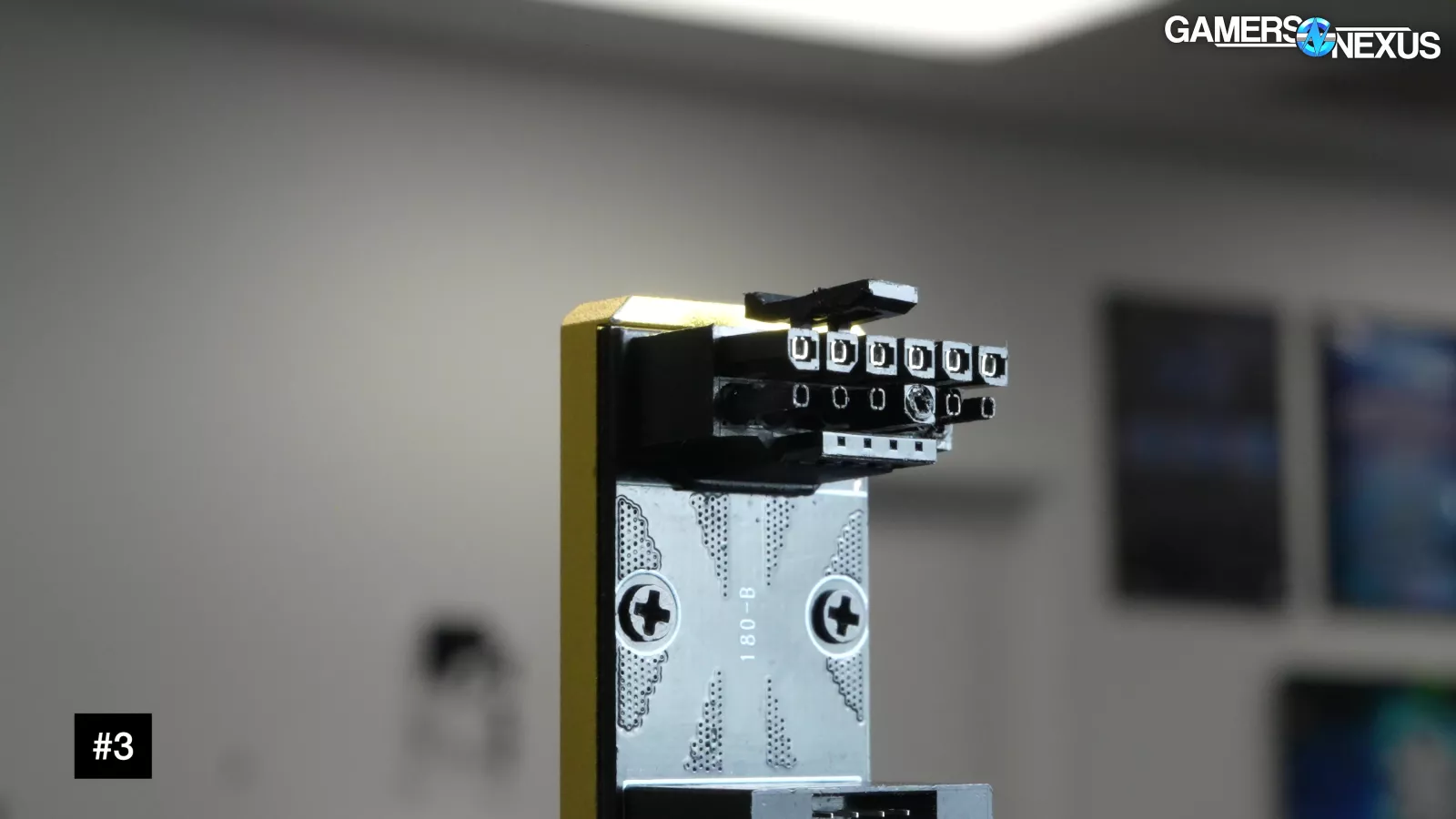
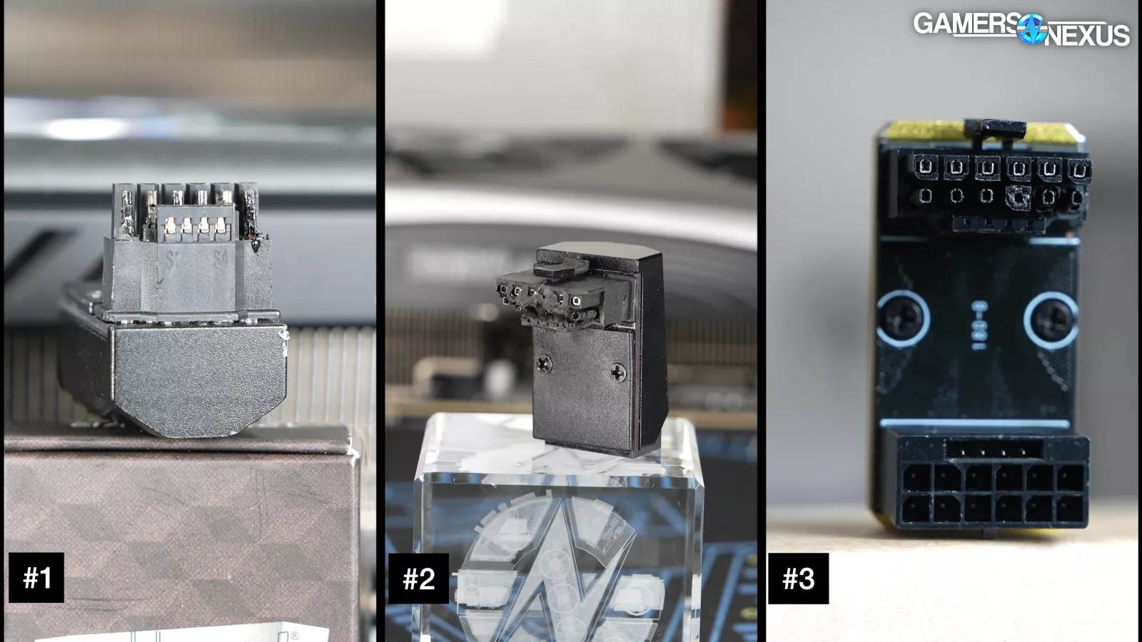
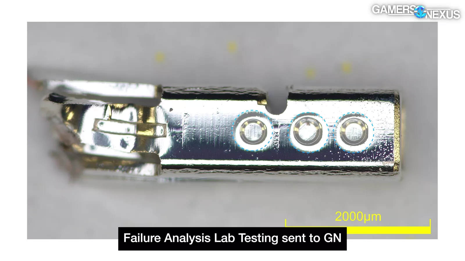
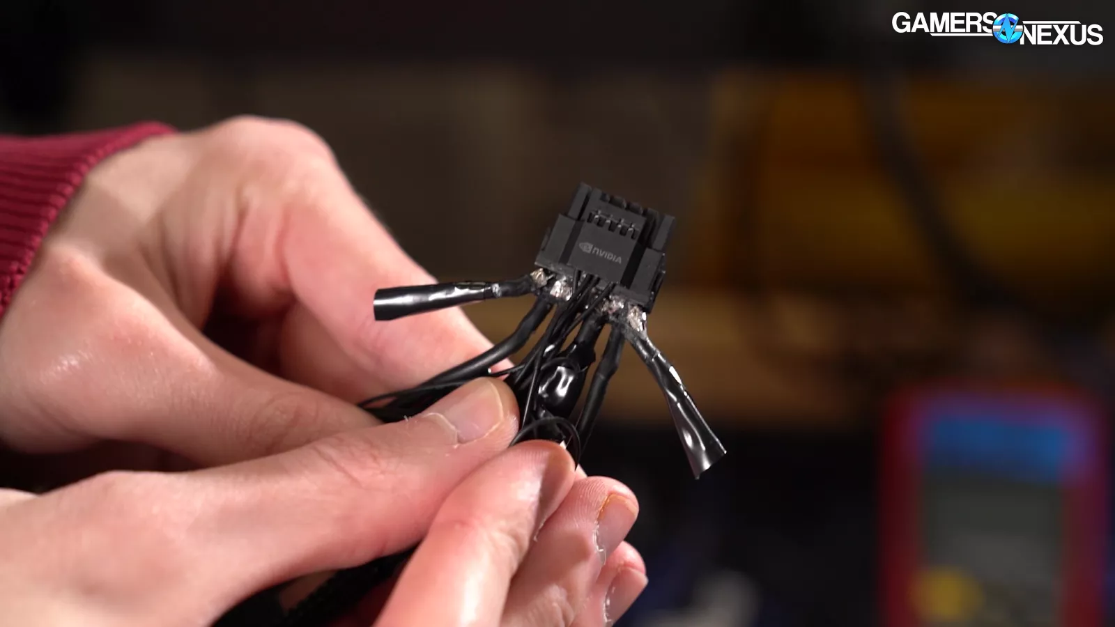
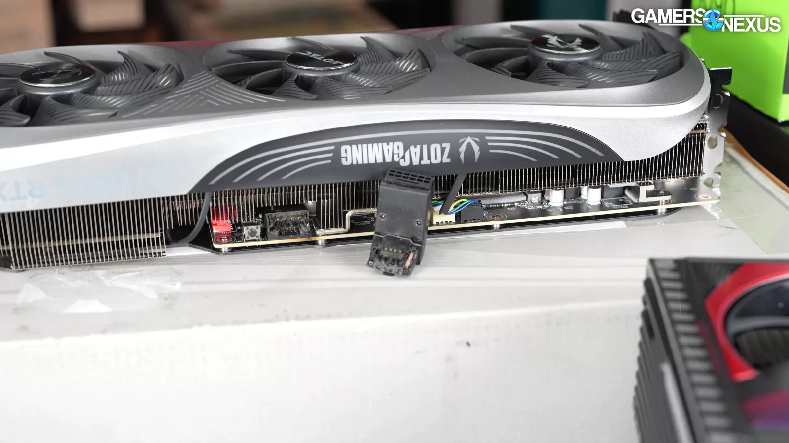
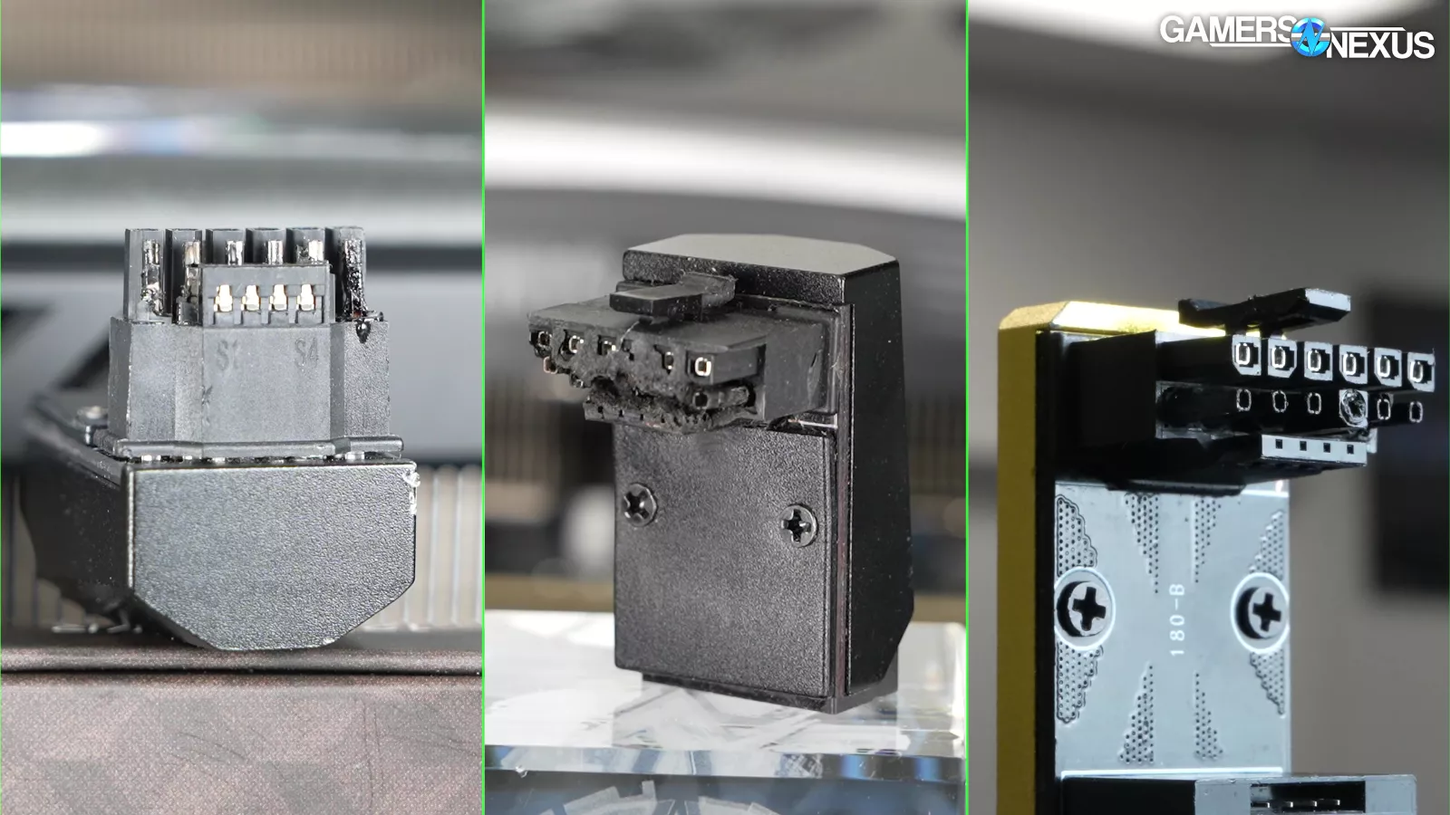
We sent three CableMod angled adapters to a failure analysis lab: one 90 degree variant B (#1), one 90 degree variant A (#2), and one 180 degree variant B (#3).
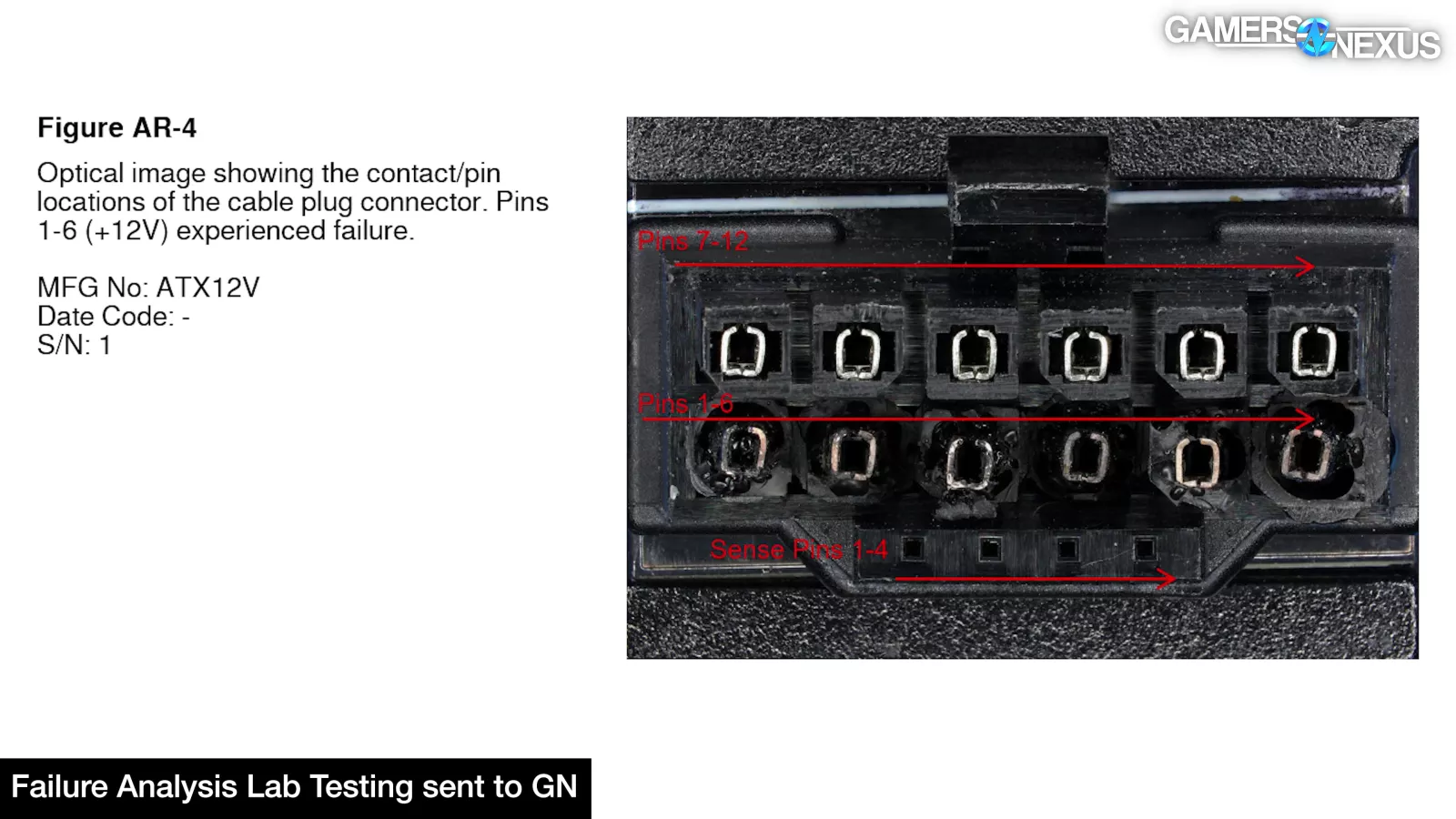
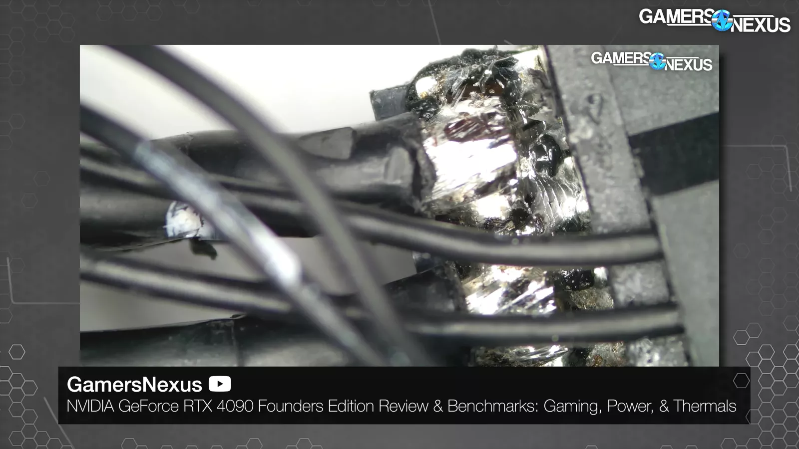
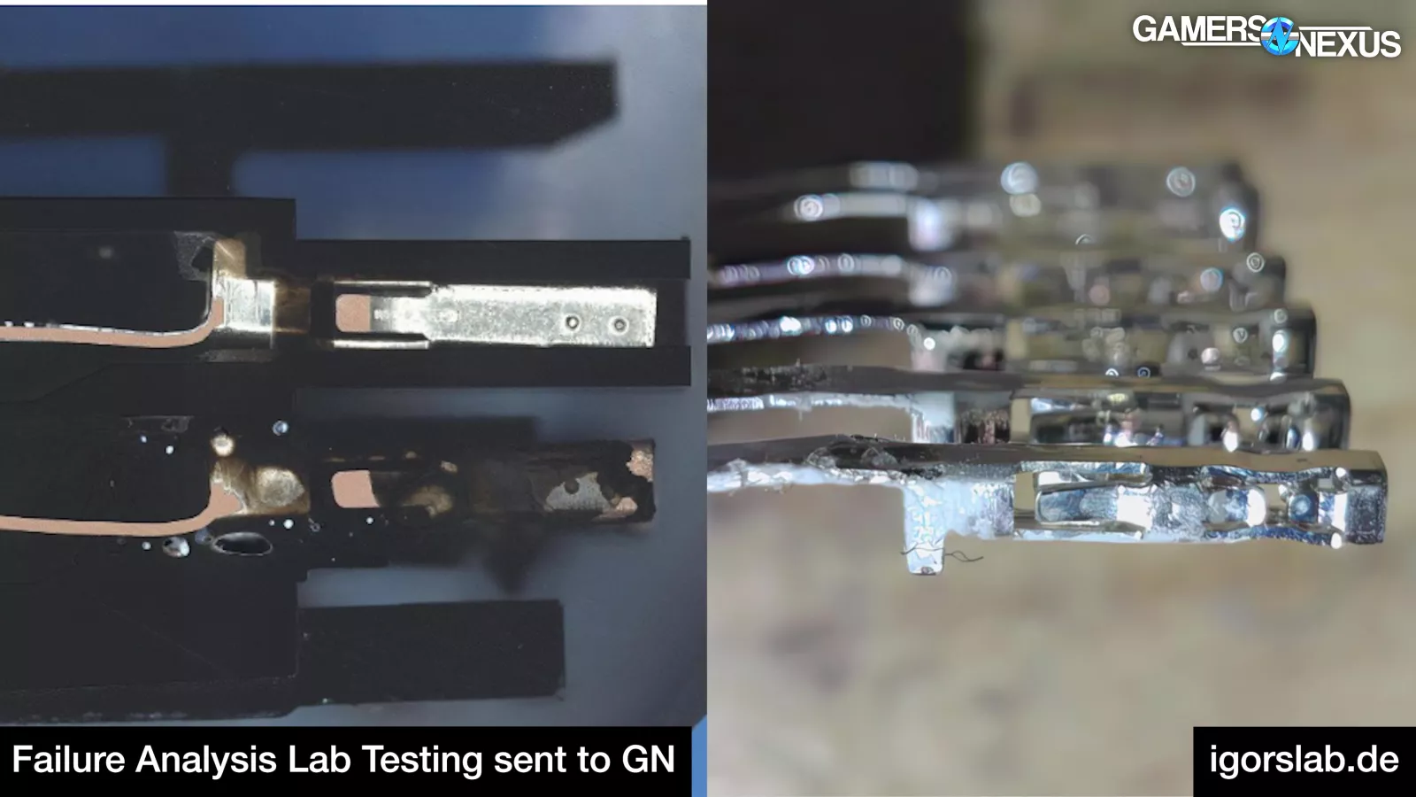
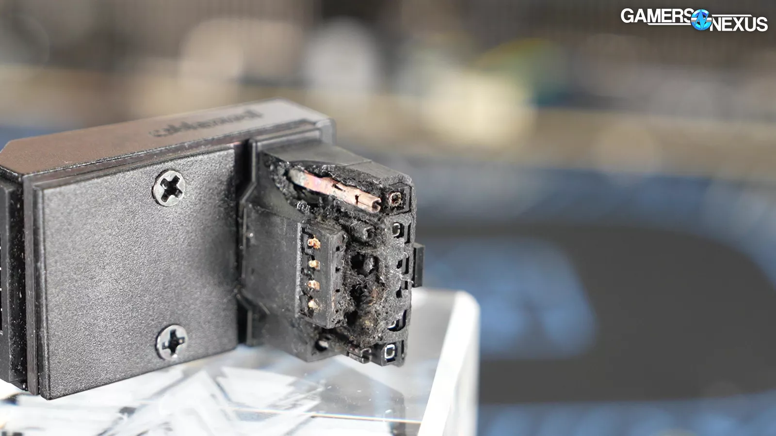
All three adapters melted around the GPU-side 12V terminals, specifically the thinner part inserted into the GPU. This implies that the area of high resistance was between the GPU pins and the male terminals, which matches the original partial insertion failures that we reproduced.
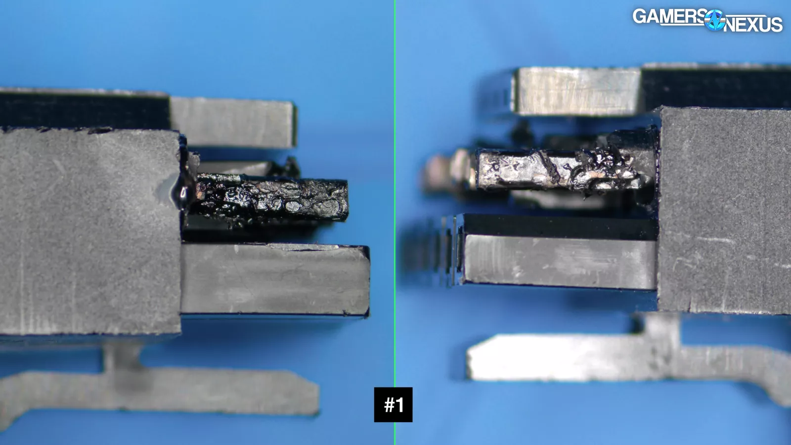
On #1, there are no obvious markings.
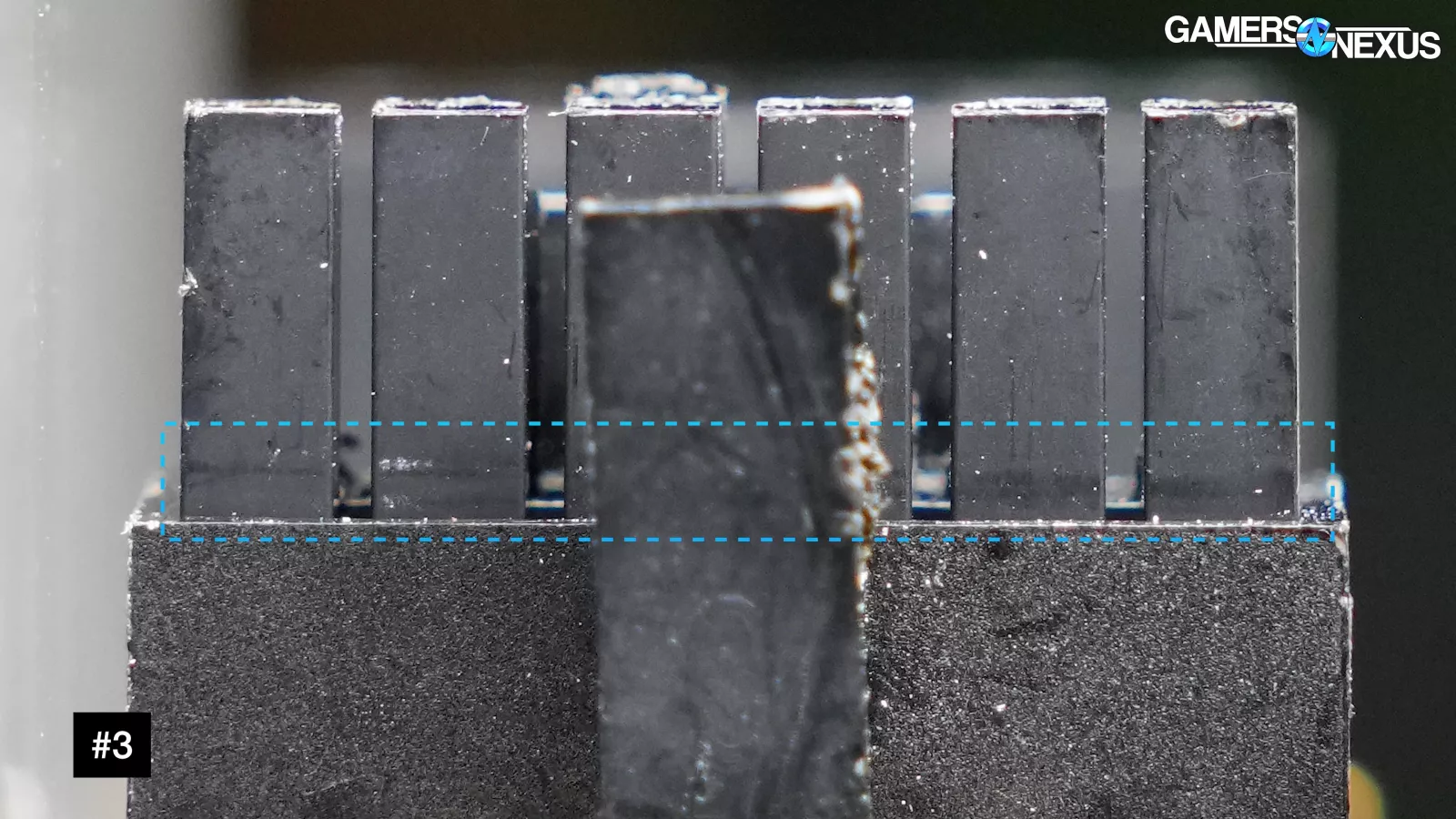
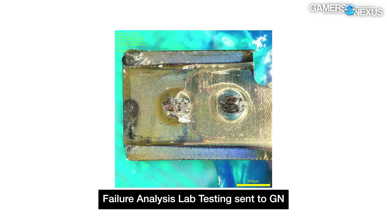
On #3's ground pins, there's a wear mark that indicates a gap of about 0.8mm, which is small enough that it could have been created even with the retention clip in place.
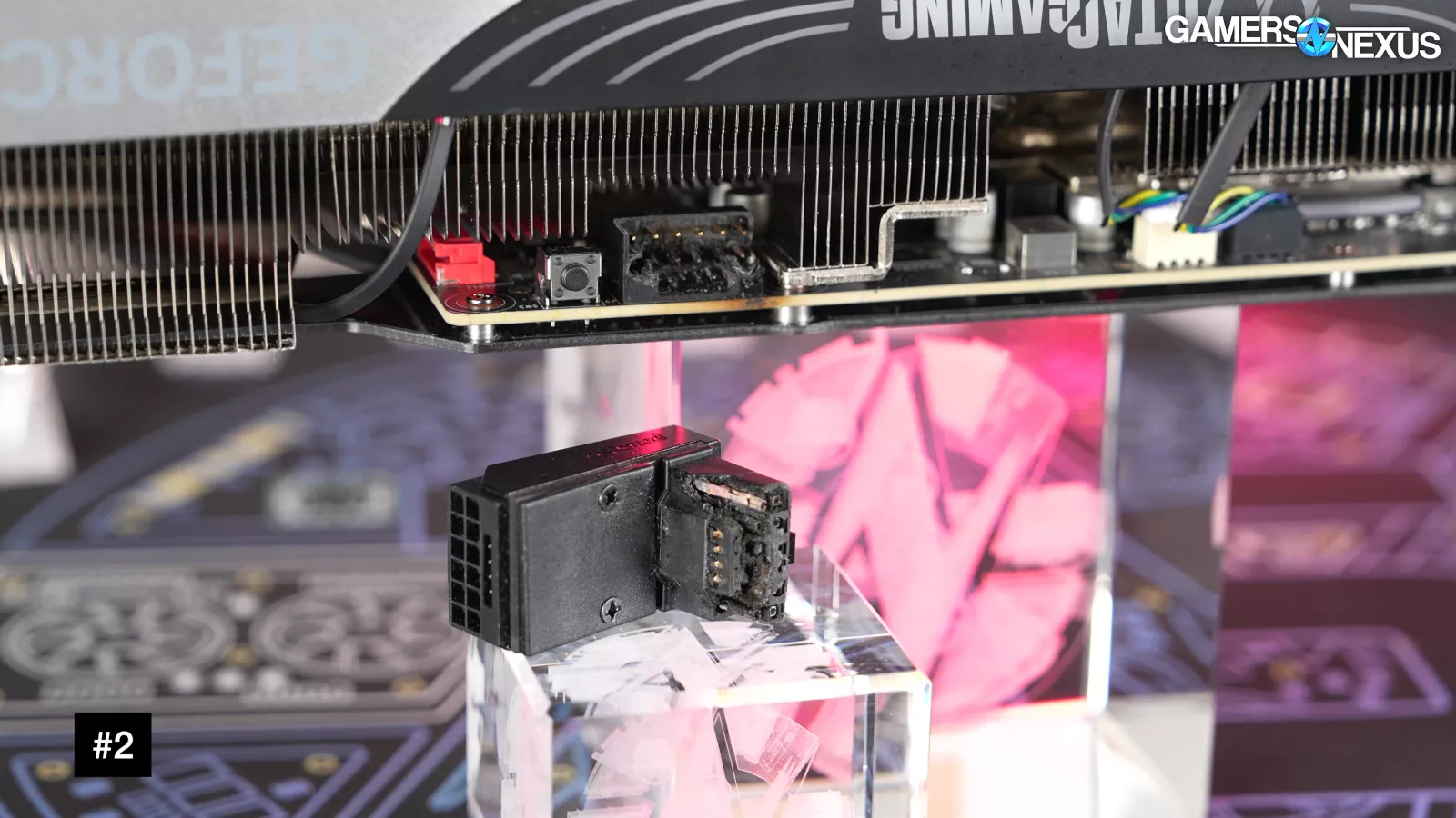
On #2, we know the connector was 100% fully seated because it melted off with the adapter, so this one should be a clearer indicator as to what CableMod specifically screwed up with its adapters. We have two other pairs of GPUs and adapters that we didn't send out from CableMod, and the angled adapters on those appear to have been seated at least enough to fasten the retention clips.
So, we have five melted and later recalled CableMod adapters, and some (if not all) of them were installed correctly.
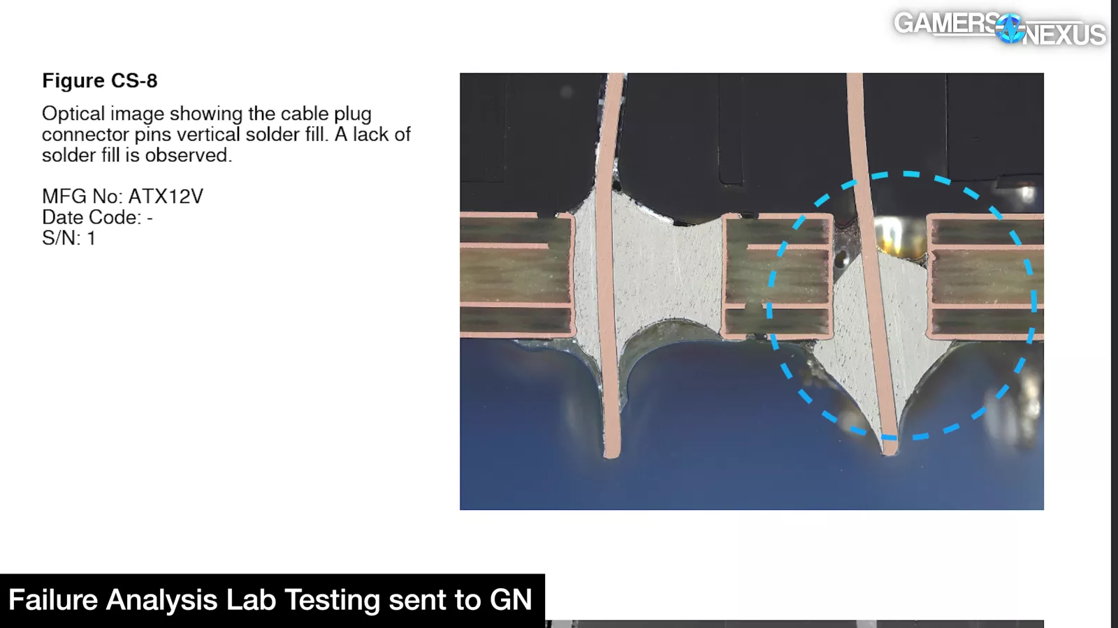
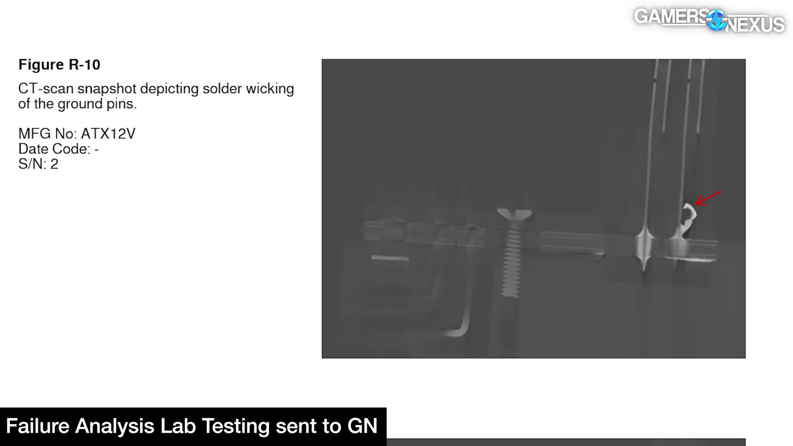
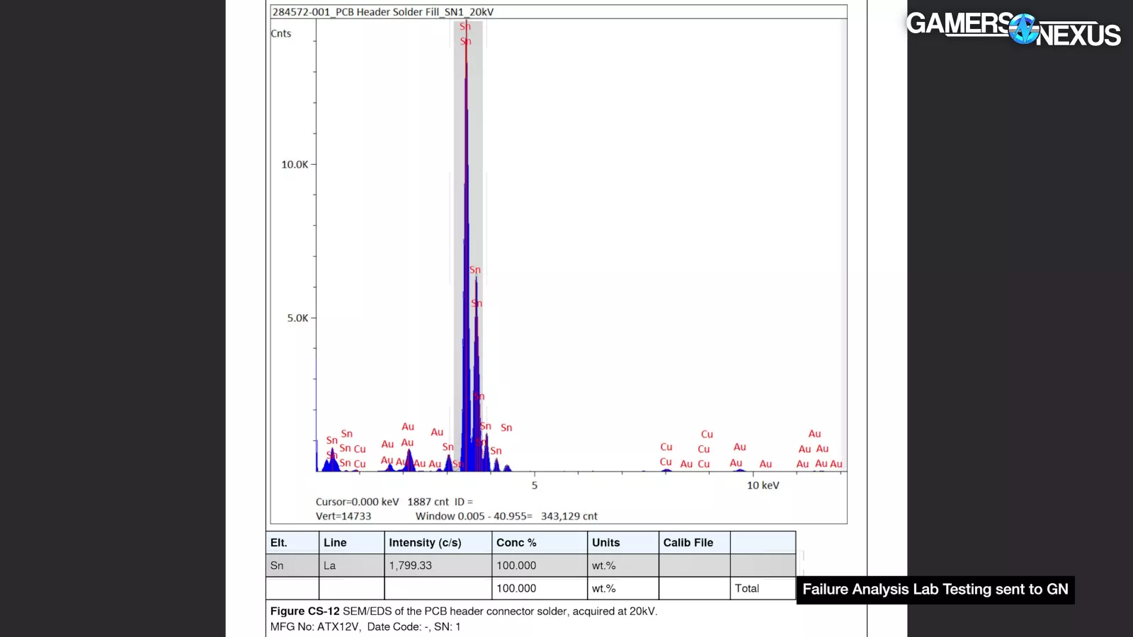
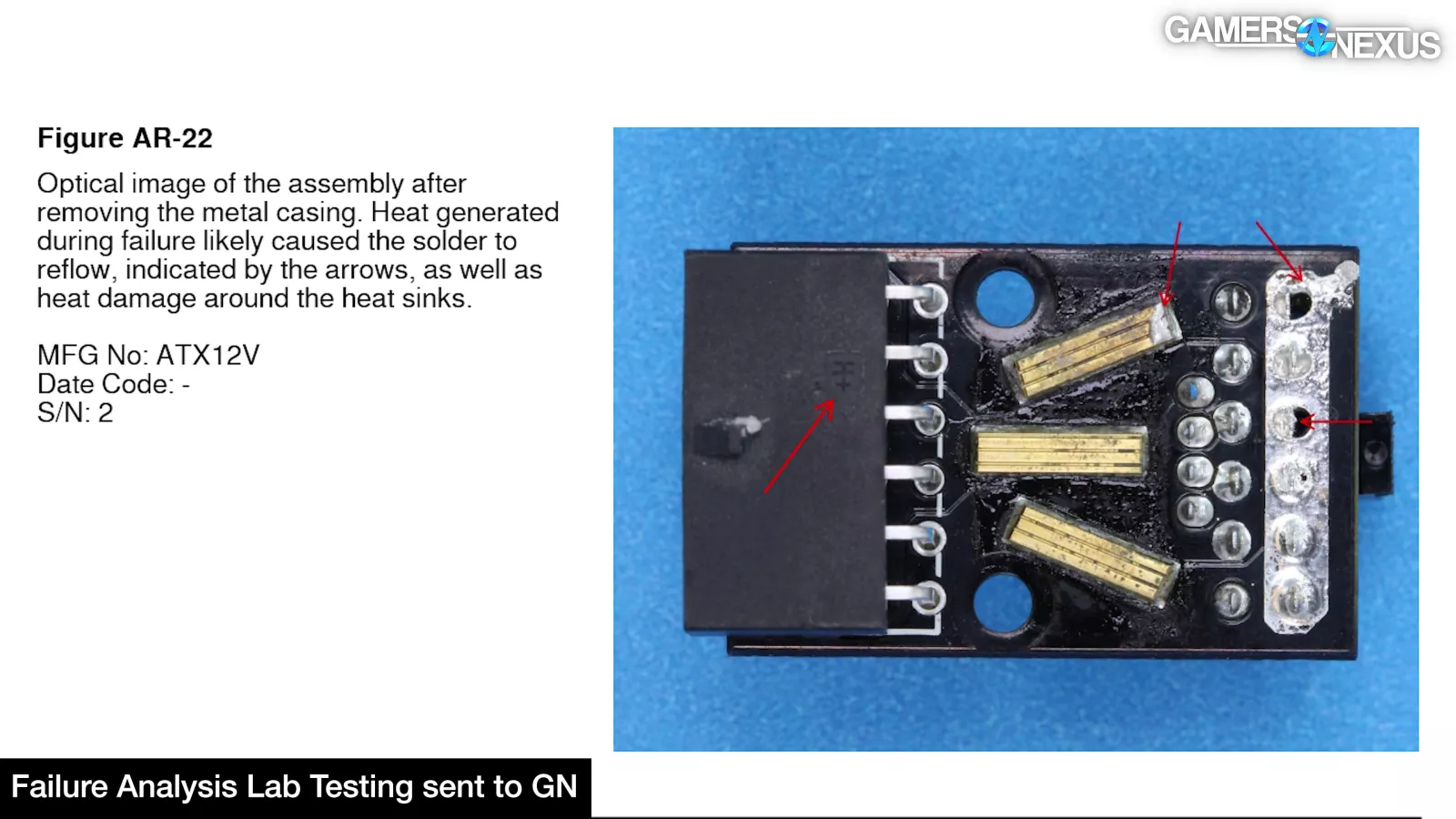
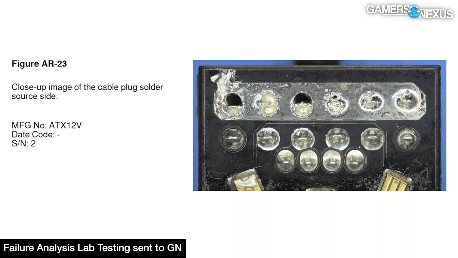
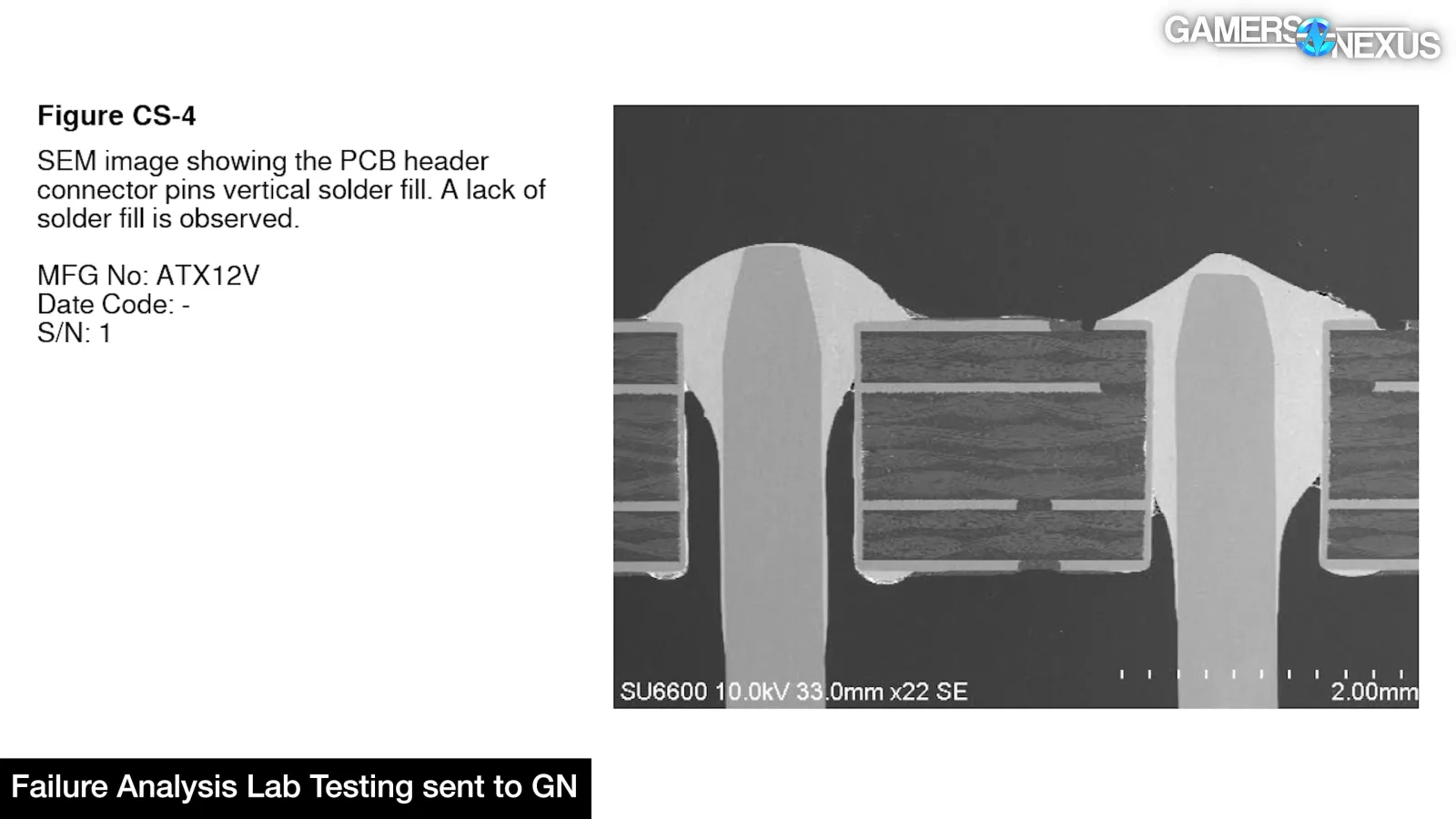
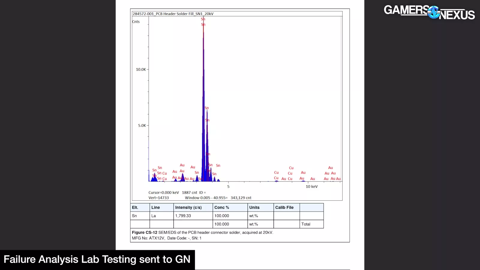
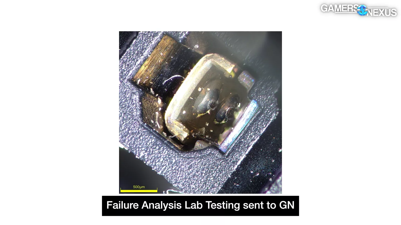
The adapters commonly had inadequate solder fill, although #2 specifically had gotten so hot that the solder reflowed away from joints. CableMod and its factory used 100% tin solder; manufacturing often requires using a lead-free solder, but it has the disadvantage of a significantly higher melting point (232C) versus tin/lead solder (183C), although it depends on a few other factors like the specific alloy composition and there’s a bit of a range.
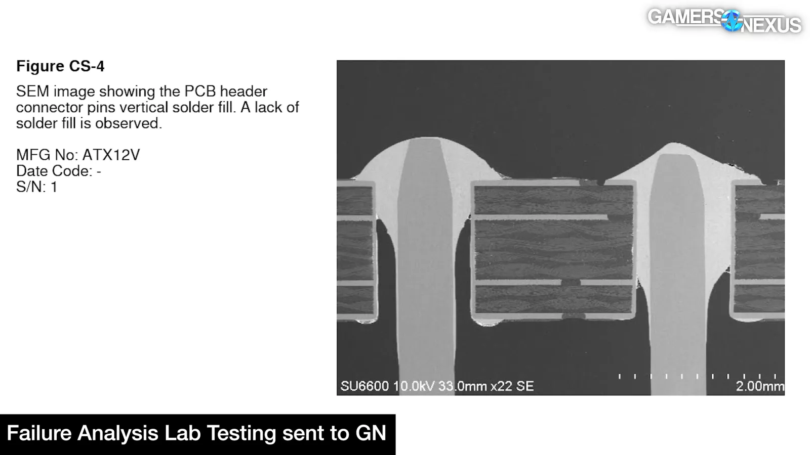
The extra-thick copper layers on the PCB combined with excessive vias and big copper bars would have made it very hard to heat the angled adapters enough to flow tin solder and wet the mating surfaces.
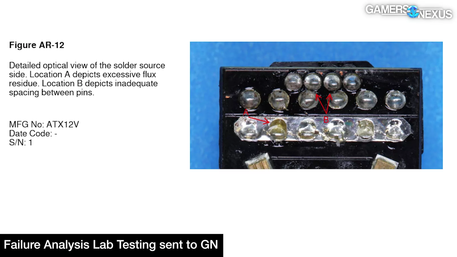
This may explain the excessive flux that the failure analysis lab we hired identified on #1, which could cause electrical issues depending on the flux used and the amount, according to the lab. Bad solder fill and flux are problems, but as we concluded during the original 12VHPWR investigation, the point of failure wasn't at a solder joint.
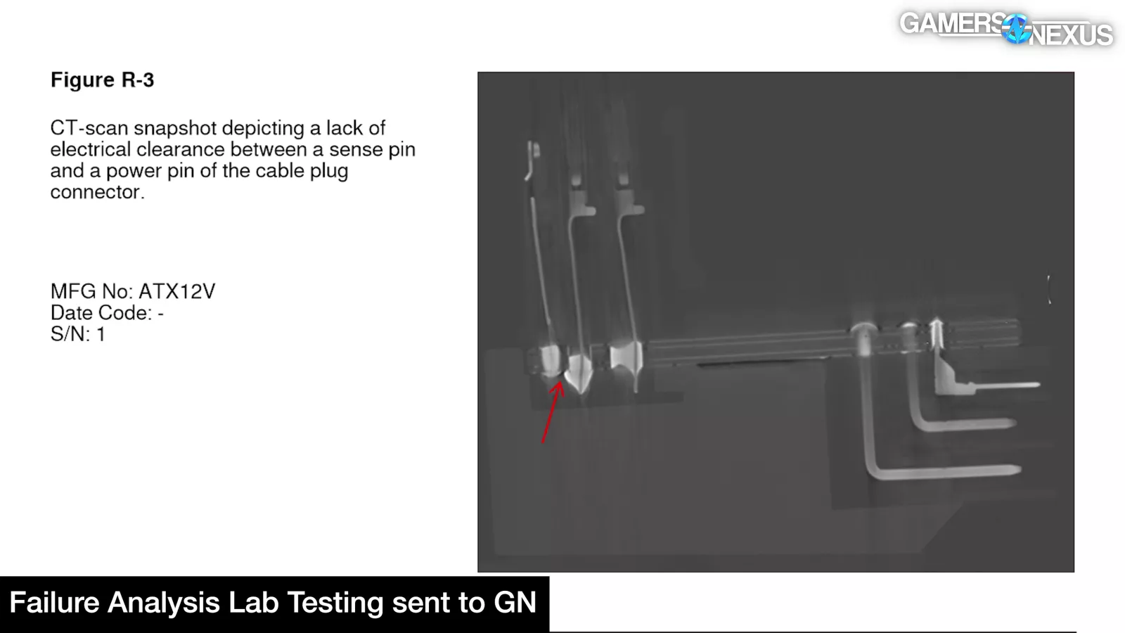
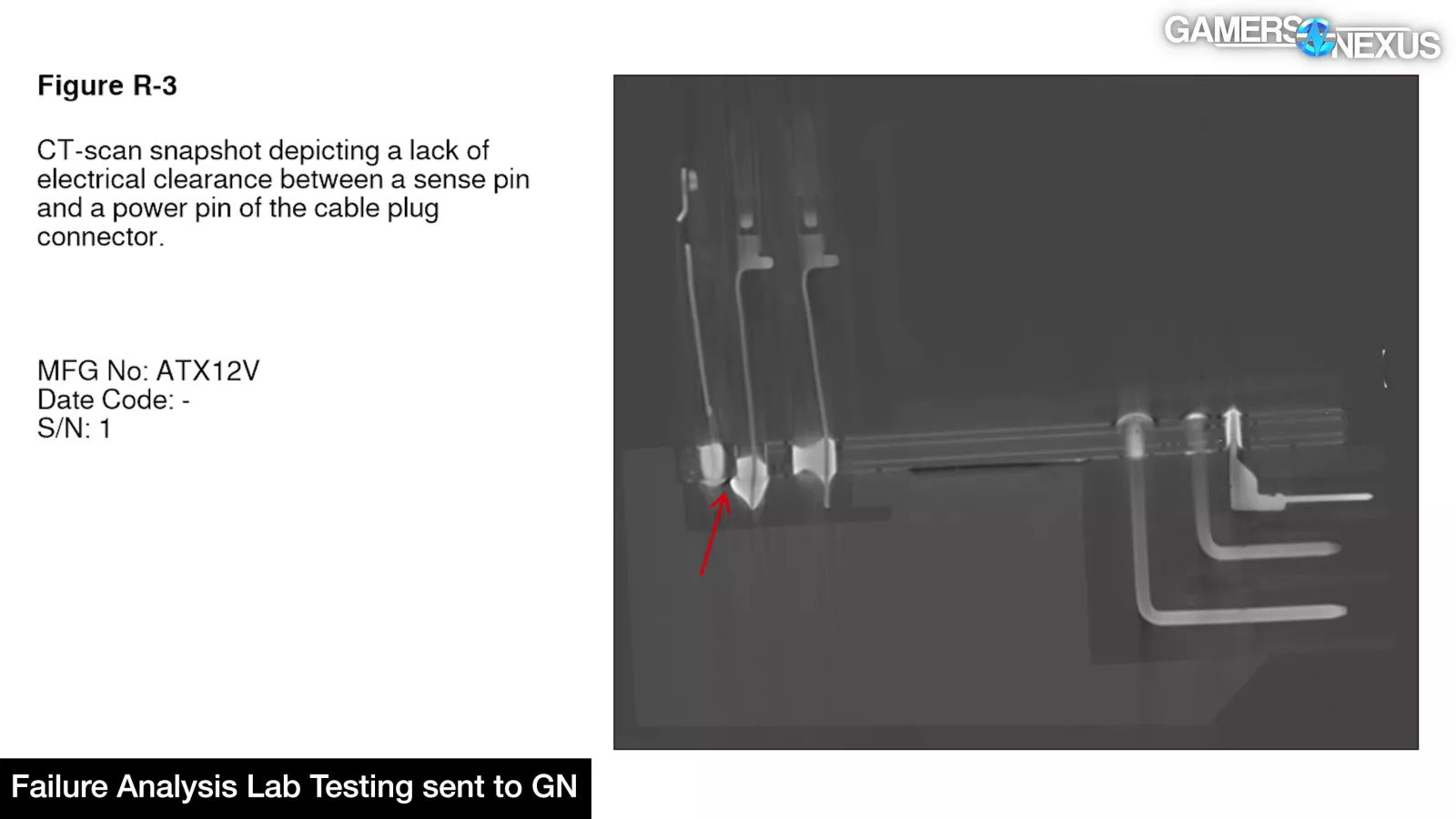
The clearances between the solder pads for the sideband pins and 12V pins on CableMod’s adapter are not adequate. The pads practically overlap here. You can see it pretty clearly. This combined with manufacturing variance or tolerances could lead to disaster and may have contributed to the CableMod recall. In the instance of our units though, this isn't good design, but it also didn't lead to our specific failures.
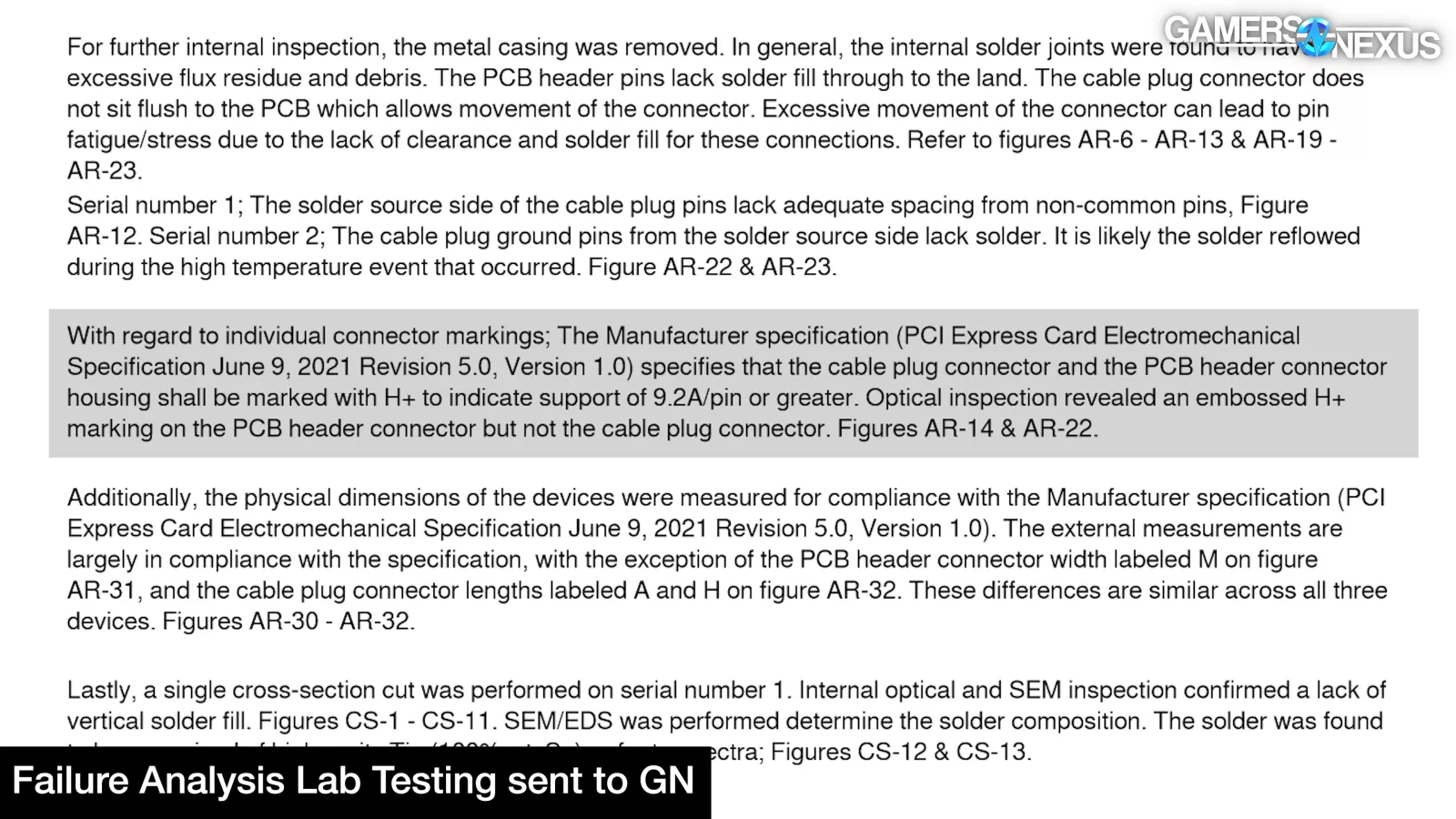
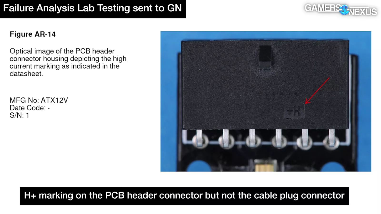
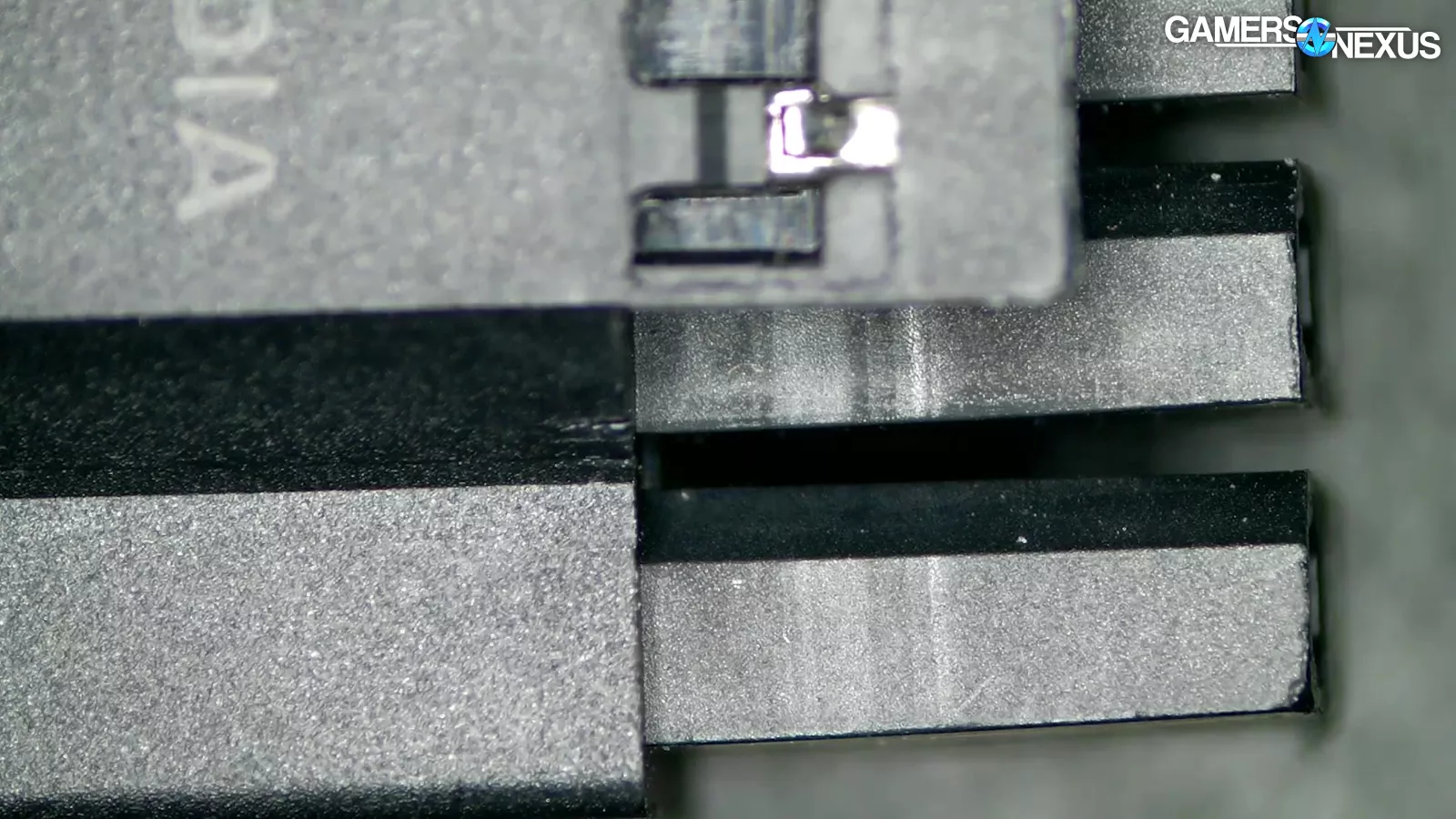
The lab also observed that the male connector lacks the proper H+ stamp that would signify a 9.2A per pin rating as laid out by the spec, but so do the NVIDIA adapter dongles that shipped with our ASUS 4090s. Having a letter and a plus sign obviously doesn’t change the characteristics, but may indicate process control or communication issues.
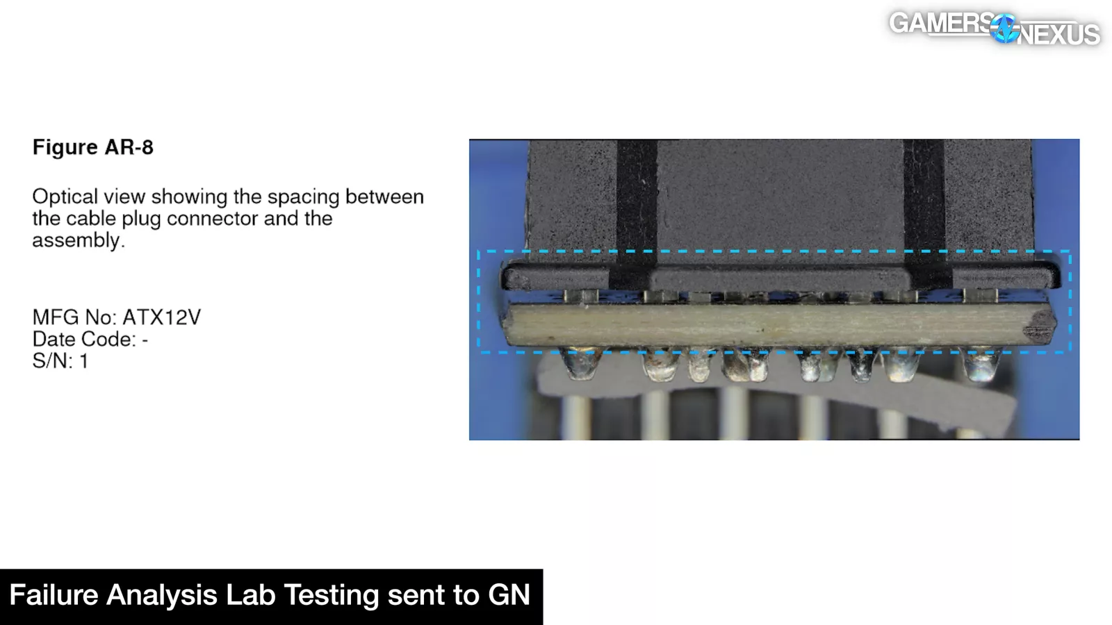
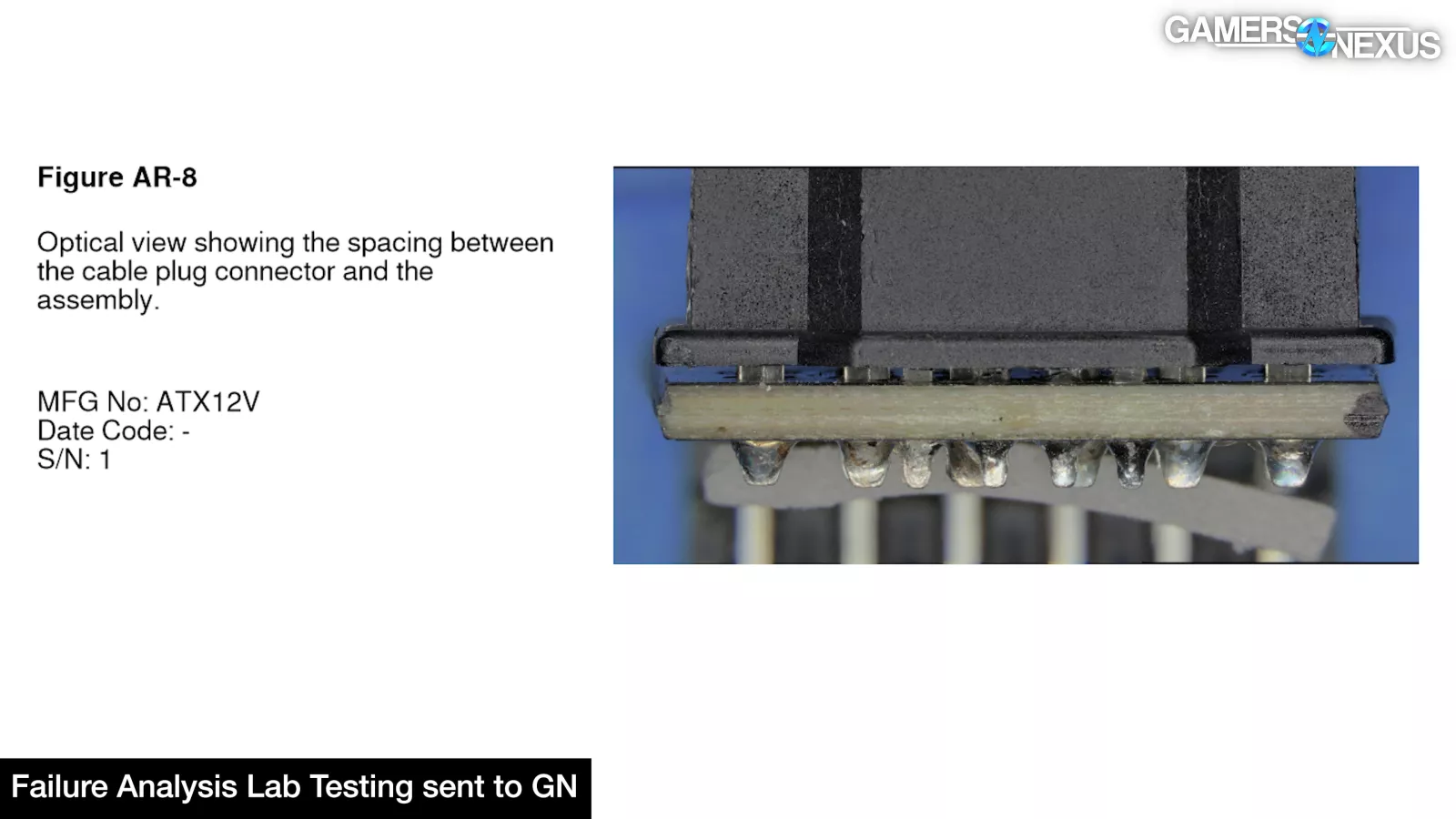
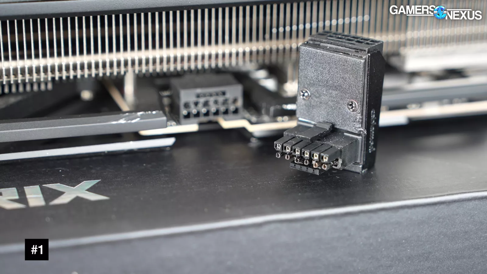
The failed adapters we sent in left too much space between the male connector and the PCB, allowing the connector to wiggle on its pins, which is the issue that CableMod tried to address with later 1.1 adapters by staking the connectors.
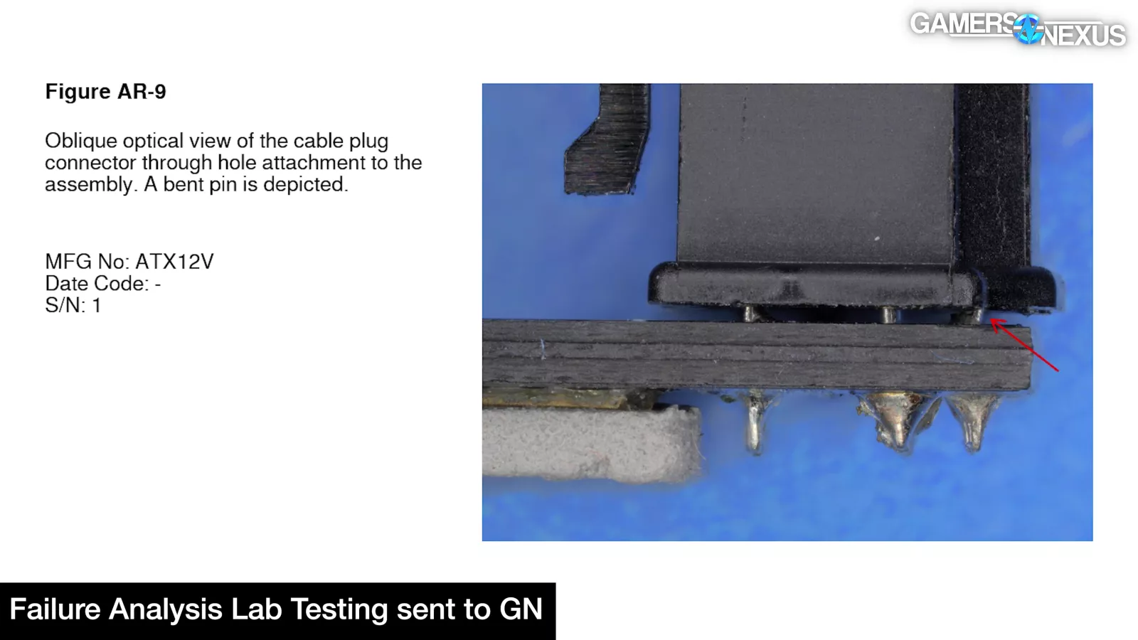
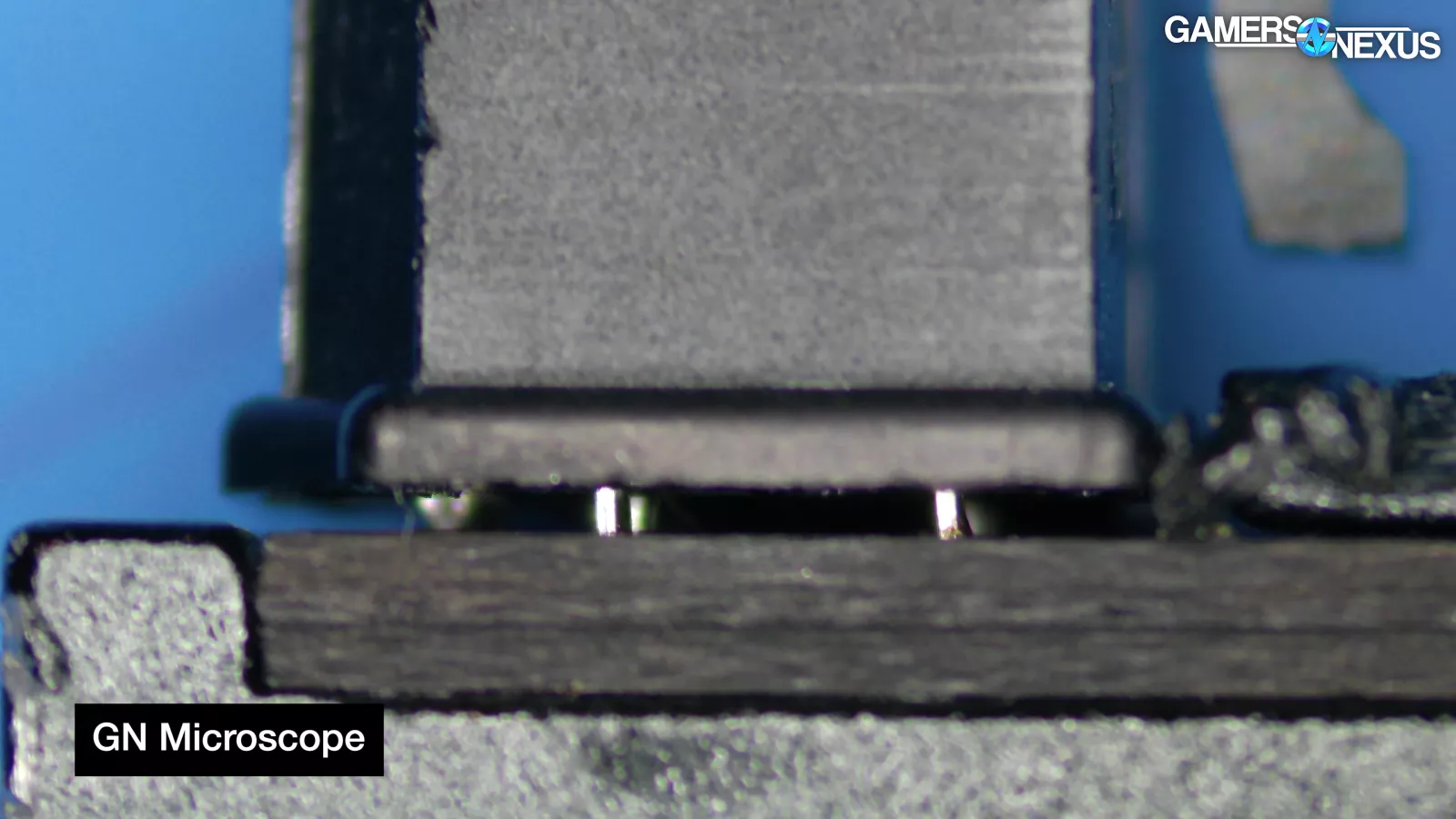
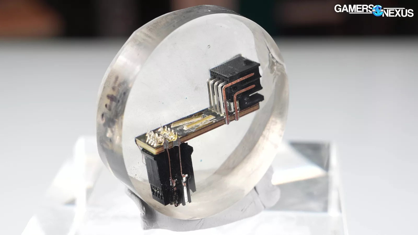
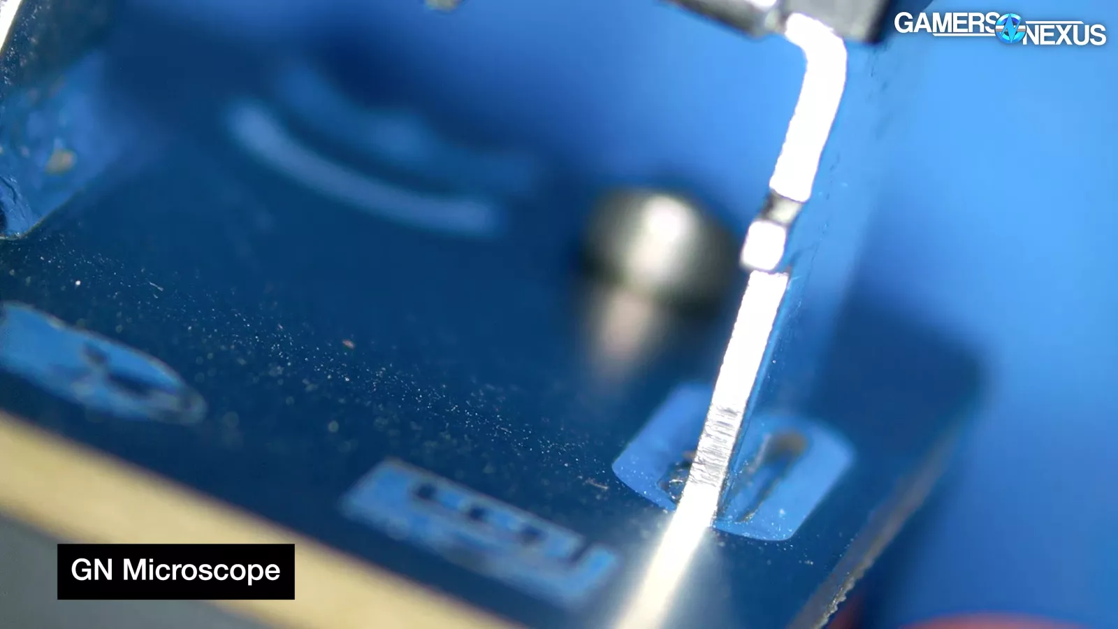
Flexing pins could lead to fatigue and work hardening over time. In #1, a sideband pin was visibly bent at the PCB. In fact, the CT scan of #1 shows dramatic bending of most of the pins inside the connector housing. This is bad. This is also visible in the epoxied cross-section that the lab performed. Some of this may have happened when prying the melted connector out of the GPU, but the fact that it could happen at all is telling.
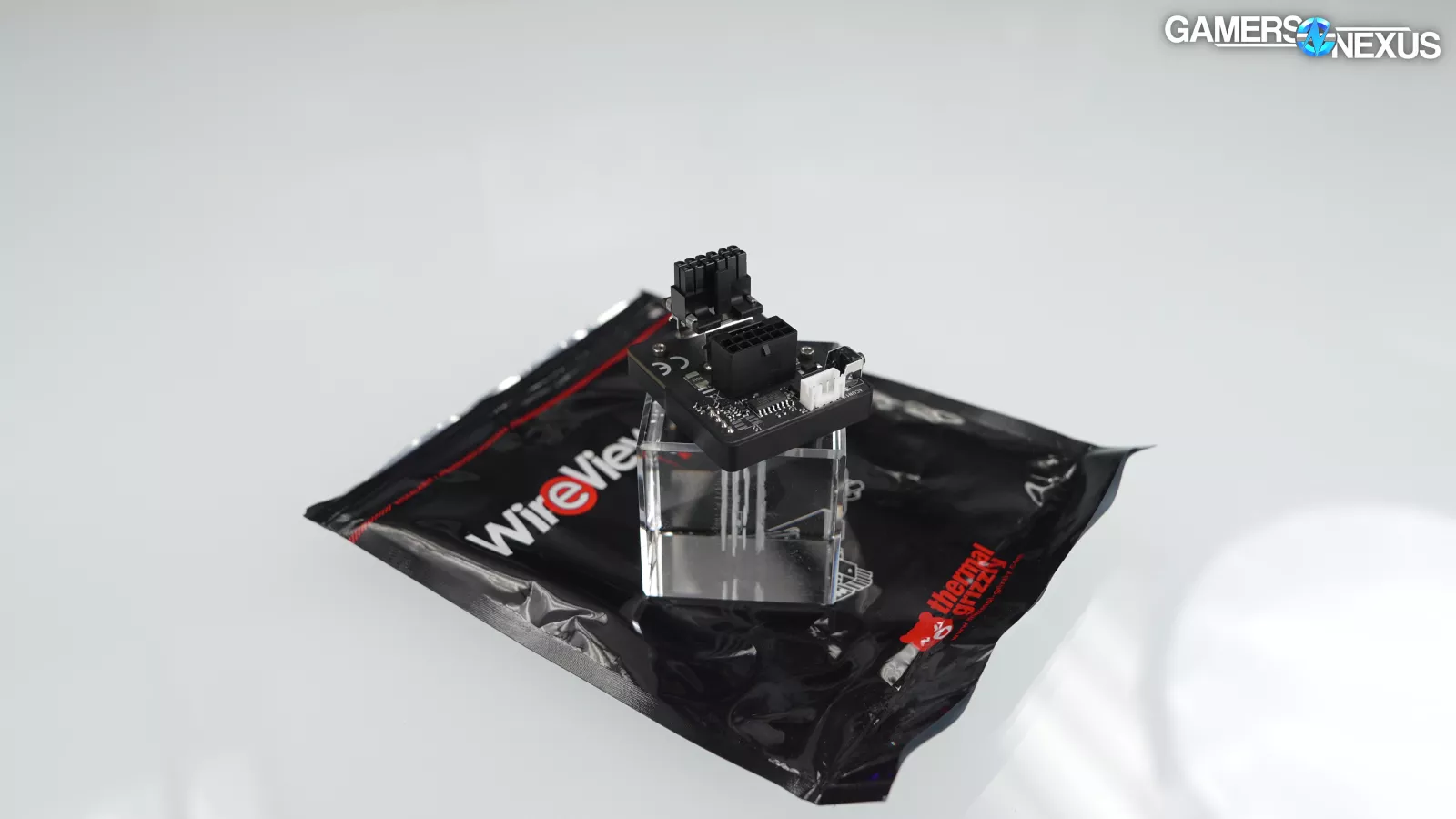
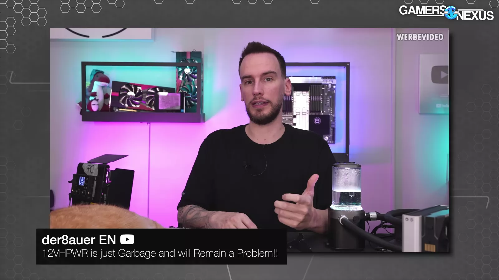
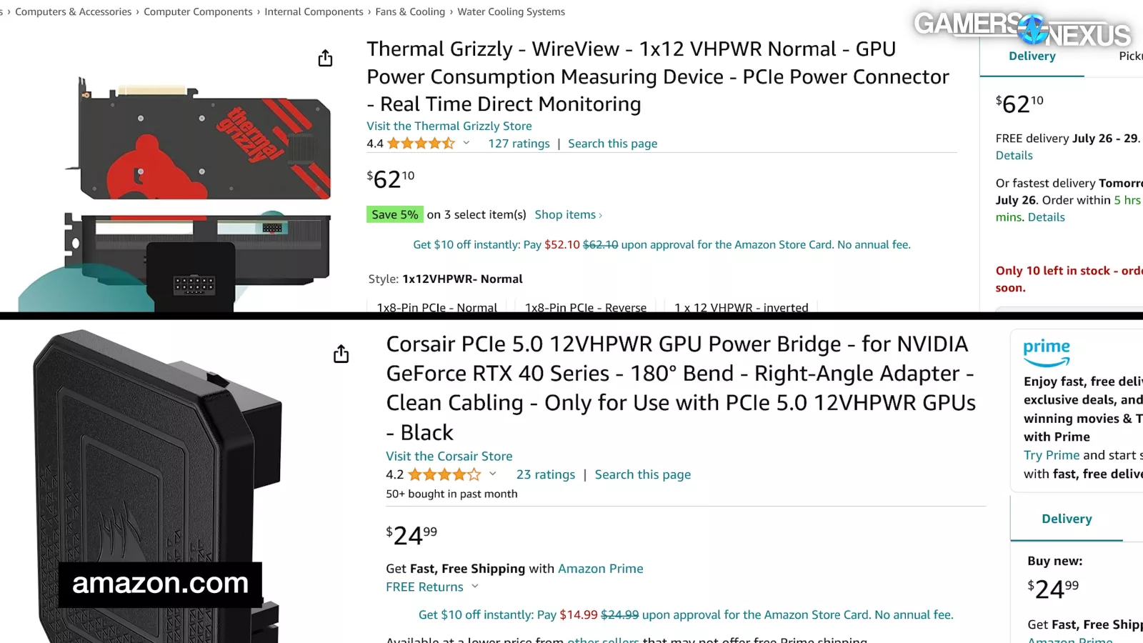
Thermal Grizzly produces the WireView in collaboration with ElmorLabs. CEO Der8auer ran a video on New Year's Day 2024 entitled "12VHPWR is just Garbage and will Remain a Problem!!" where he stated that "Nobody that is selling any kind of product that comes with any kind of 12VHPWR adapter can guarantee anything. That's just how it is. You are always left with a risk that something goes wrong as long as you use this connector."
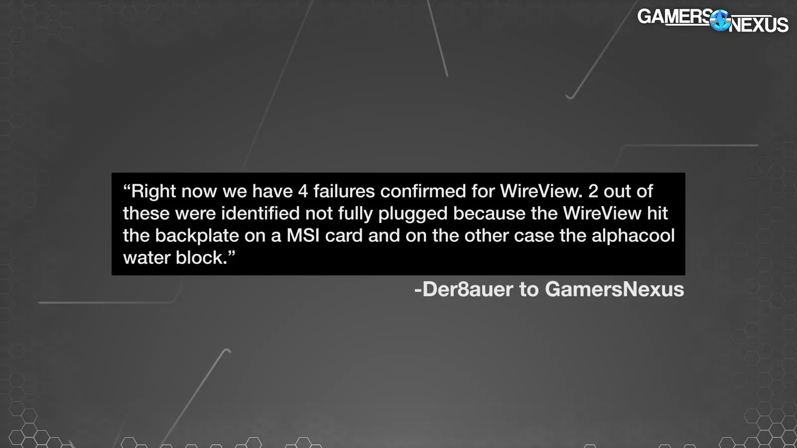
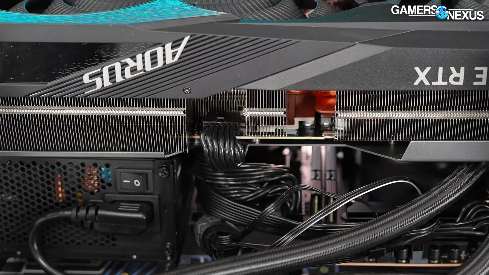
We checked with Thermal Grizzly and, at the time of posting, the company has had 4 RMAs. Der8auer noted that of those, two customers were unable to fully seat the connector due to backplate and water block obstructions. There’s also a new WireView pro, which has some relevant changes to it.
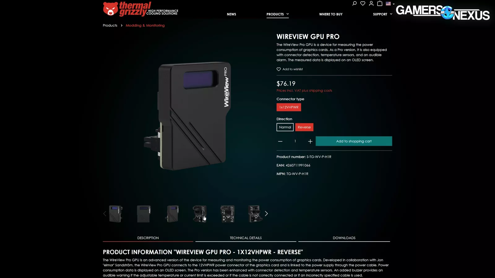
The one pictured above will have detection of the sideband pins to determine if the 12VHPWR connectors are fully plugged in. It also has temperature sensing at the power connectors and it has hookups for external temperature sensors; further, they’ve added an audible alarm that’ll sound when an incorrect cable is installed, there’s improper insertion, or when user designated current or temperature limits are exceeded.
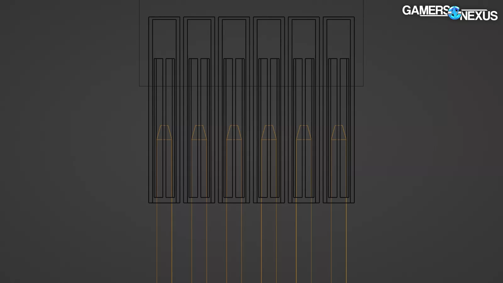
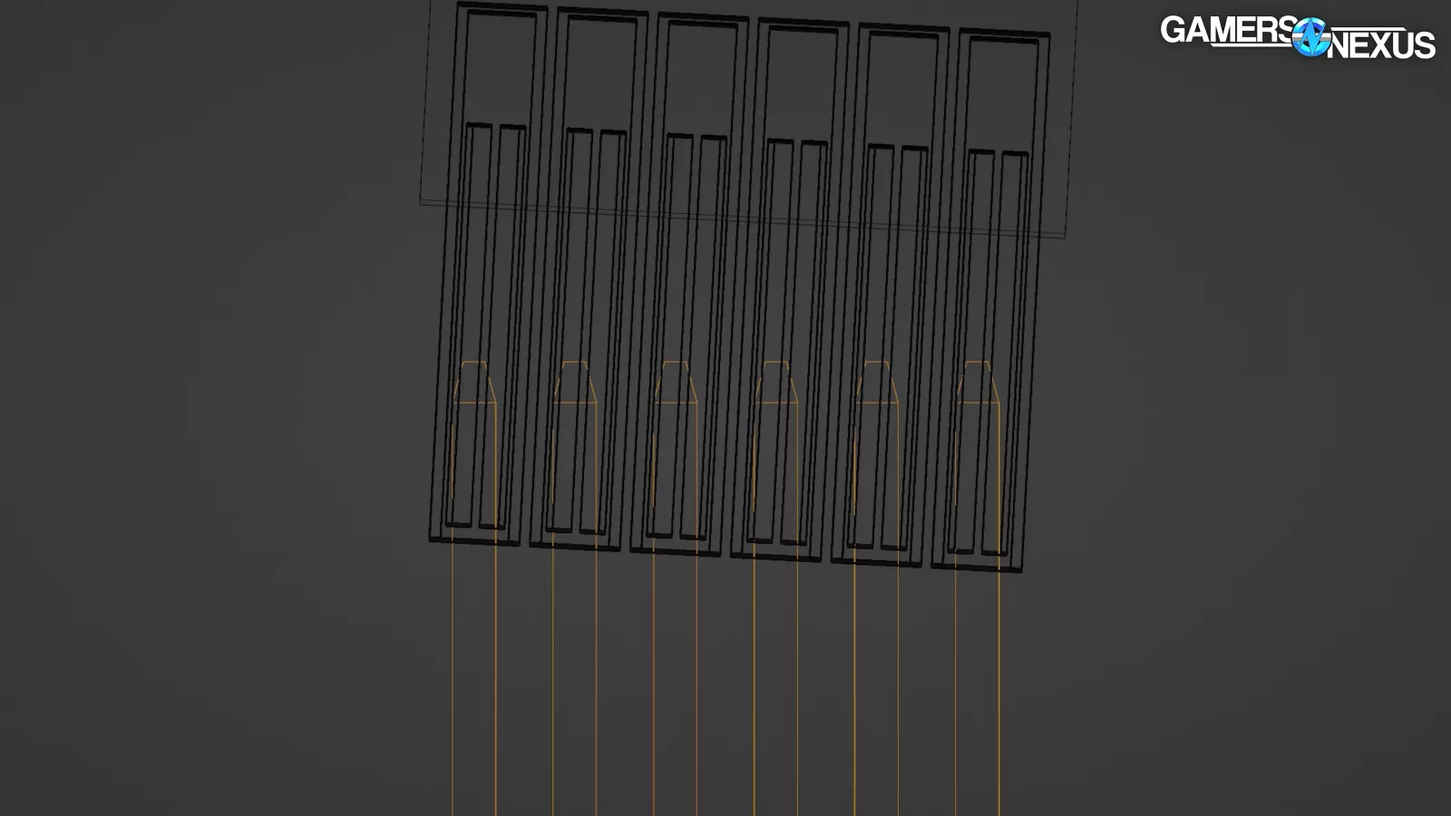
The original WireView completely skips soldering the sense pins and just jumps them internally, and on the male connector, the 12V and ground pins are soldered to two common bars that project out from the PCB. Pad spacing and solder fillet concerns are minimized because of this.
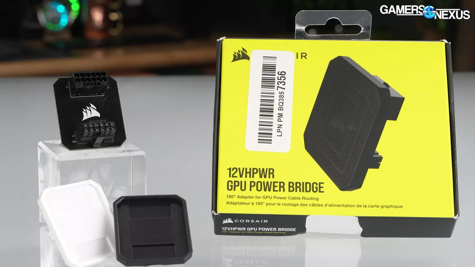
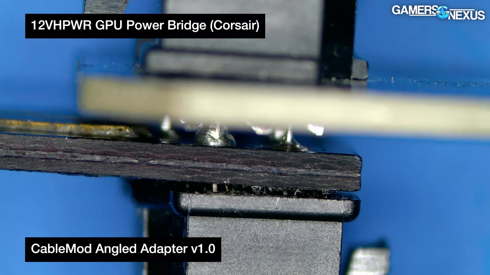
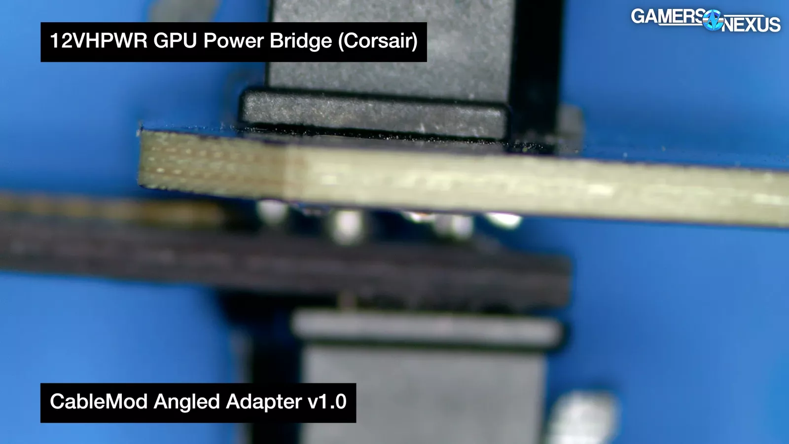
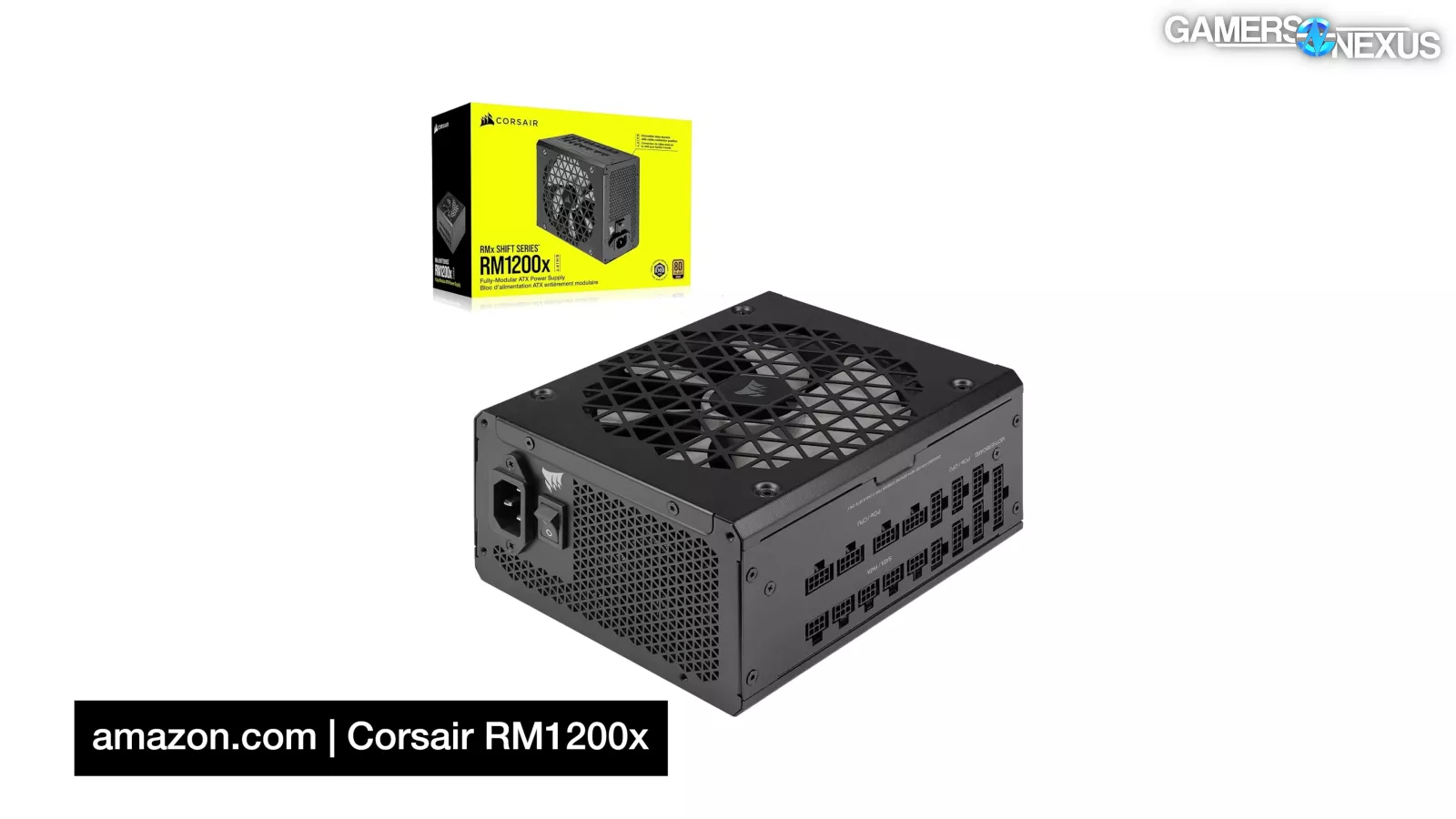
Corsair sells a "power bridge" and we've seen no reported malfunctions. We ordered one, and the connectors on the one we got were more flush with the PCB than on the failed CableMod adapters.
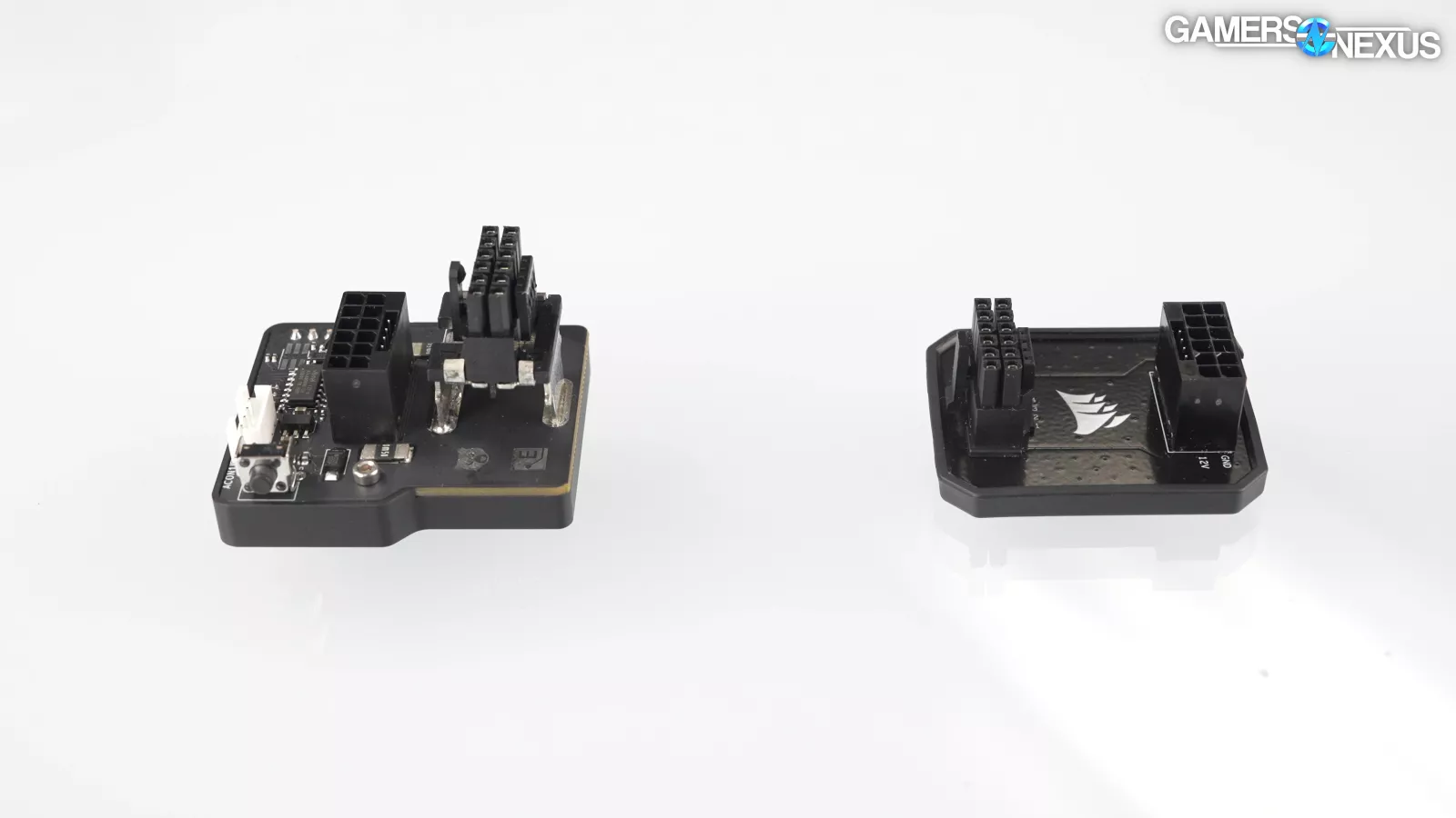
Our understanding is that CableMod outsold Corsair and Thermal Grizzly's angled adapters combined, so although we can speculate, we can't draw firm conclusions based on a lack of failures for lower volume adapters.
And this is a good time to remind everyone (including ourselves): Cables and PCB adapters are different. Angled PCB adapters predictably use a PCB, for which the spec has no official guidance.
None of these points we’ve discussed are cables other than the prior partial insertion failures we reproduced.
As for the CableMod adapters, the failure analysis lab stopped at observations, leaving some of the speculation to us.
We believe the lack of solder fill and the space between the PCB and the connector may have encouraged the terminals to flex in their housing, worsened by the leverage that's placed on angled adapters by taut cables. In combination with this, anchoring the terminals to the PCB prevented them from twisting to conform to the pins on the GPU side.

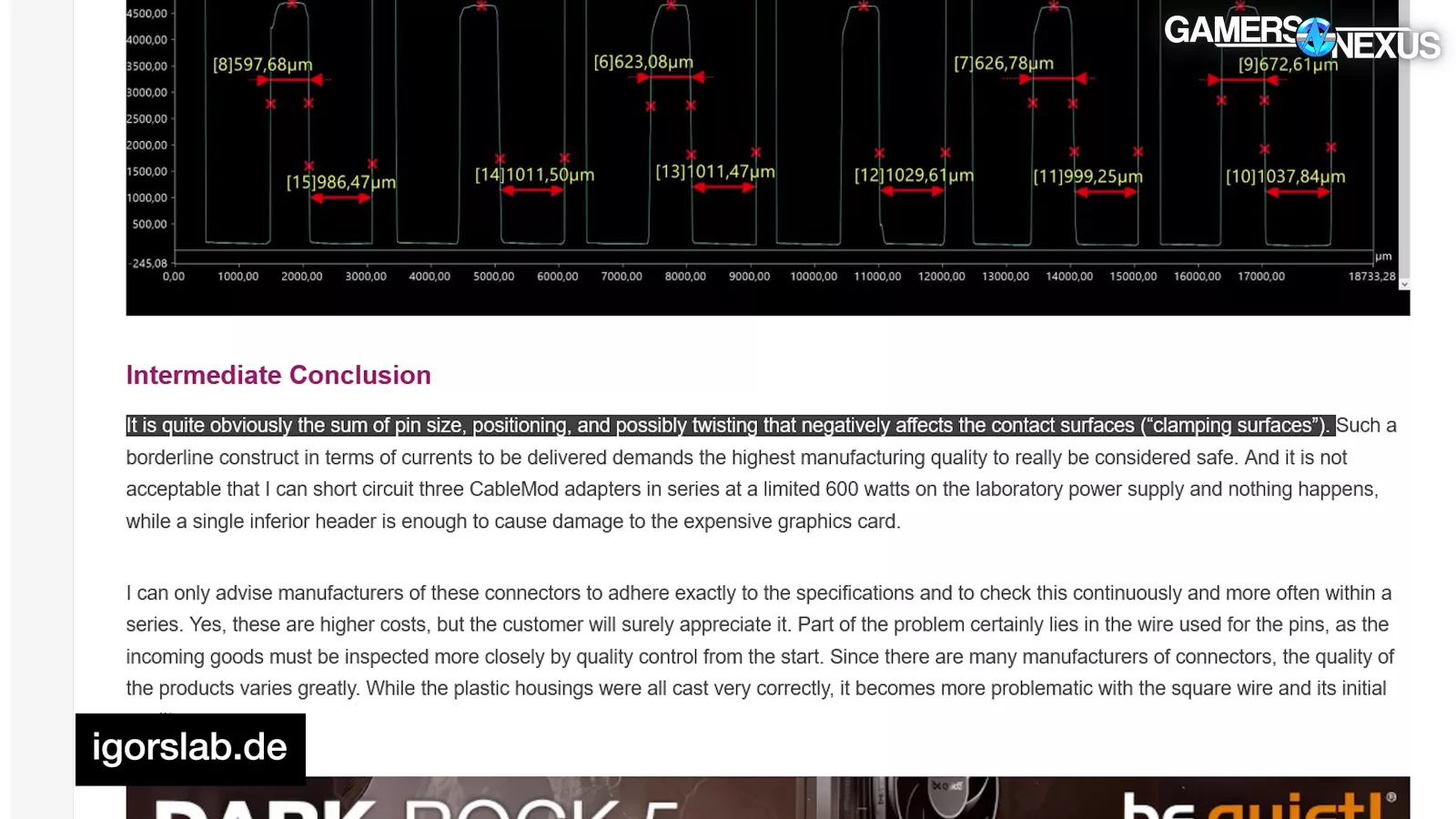
We don't entirely agree with Igor's November reassessment, but we do on that last, concluding point.
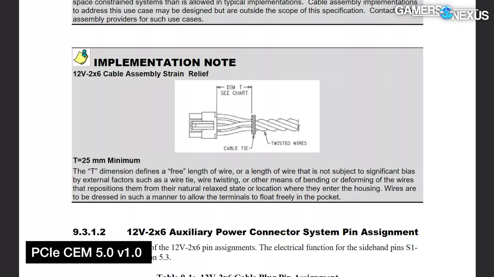
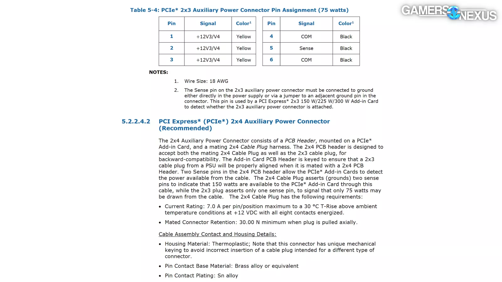
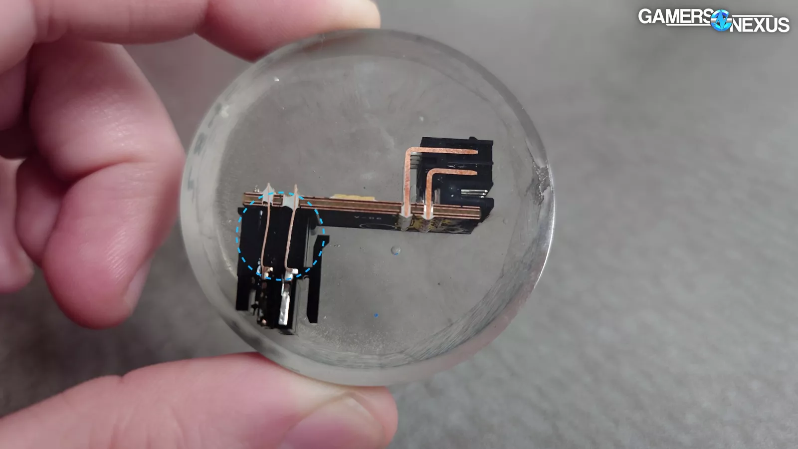
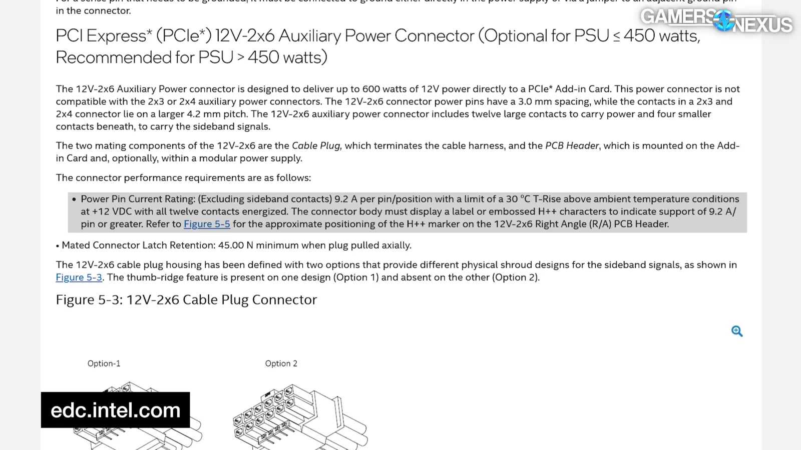
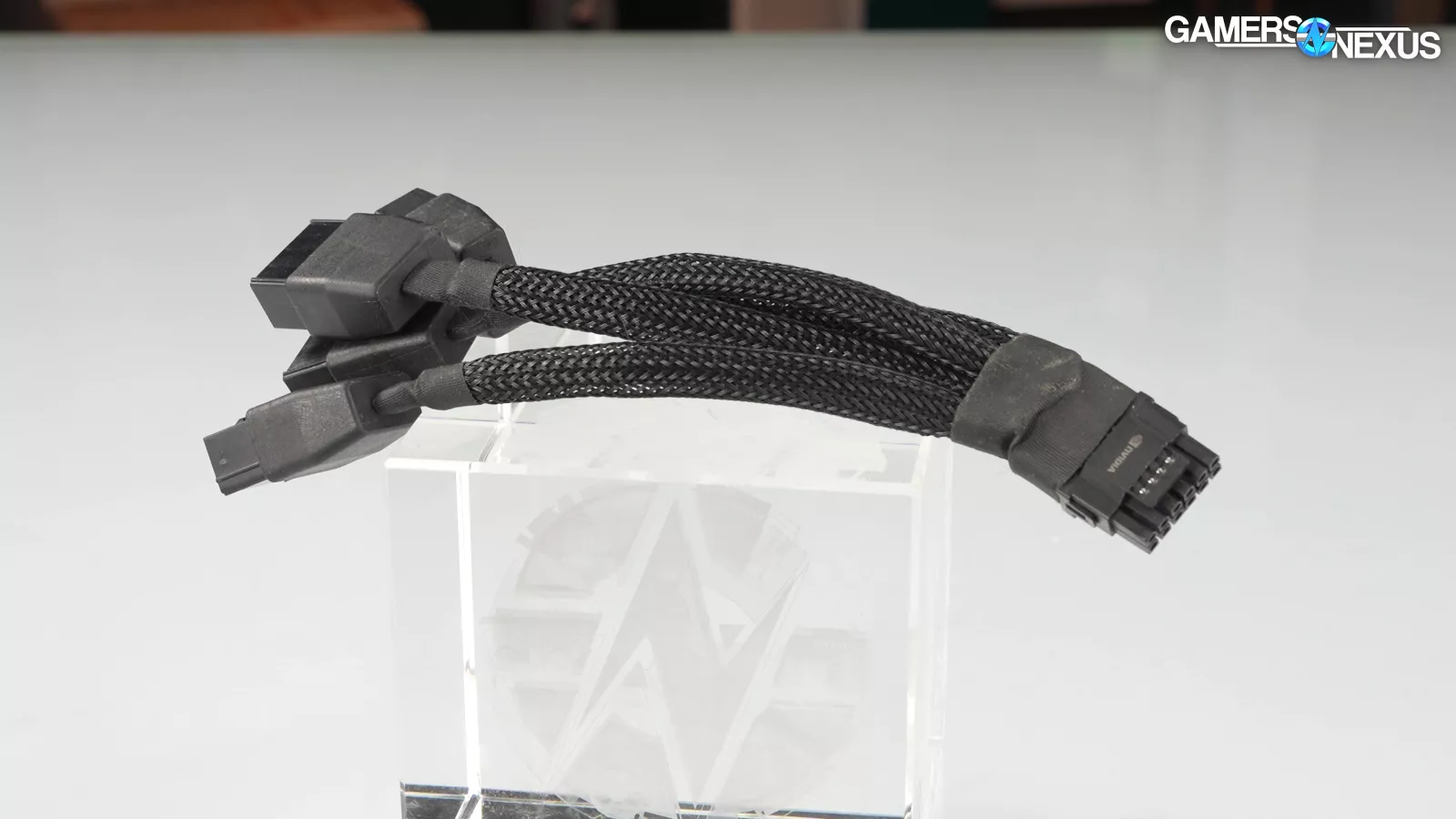
The spec for 12V-2x6 cables requires 25mm of free wire behind the male connector without anything "that repositions them from their natural relaxed state or location where they enter the housing," and "wires are to be dressed in such a manner to allow the terminals to float freely in the pocket."
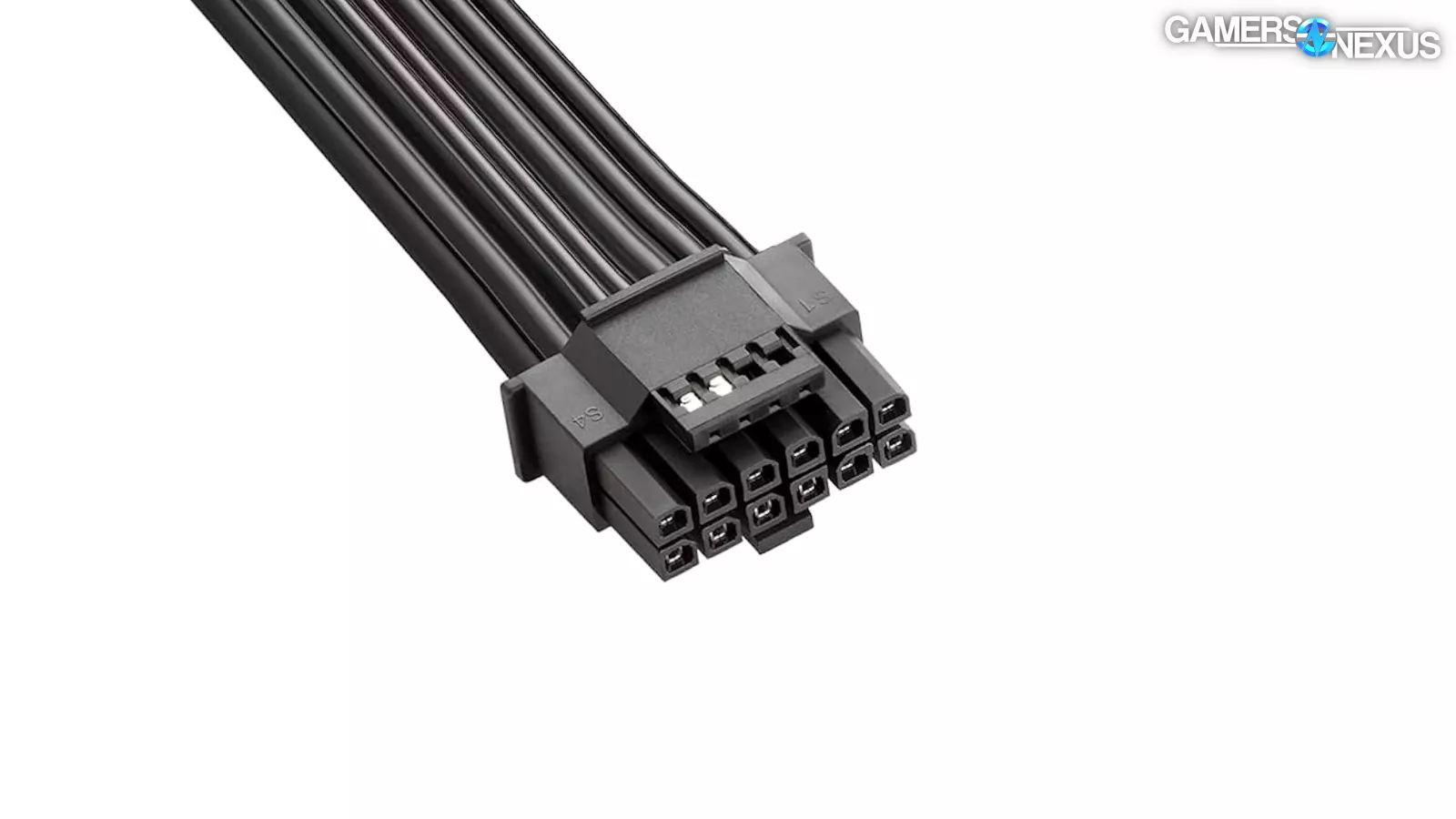
From what we've seen in the specs, this specific side of the connector (shown in the image above) is designed to be installed on a cable and is not shown mounted on a PCB in the specs. It seems possible to do so by circumventing the problem (like Thermal Grizzly), or perhaps seating the connector flush with the PCB (like with Corsair’s adapter). We're never going to guarantee that anything involving 12VHPWR is risk-free, though; we're with der8auer on that. The design oversights make that impossible. To be clear though, we also wouldn’t guarantee that PCIe 6/8-pin is risk-free -- but statistically, its risk factor appears to be at least slightly lower\ partially due to more overhead in the spec. Let’s get into that.
Part 2: Energy
Connectors melt because something causes high resistance and dumps energy as heat. In the case of the original 12VHPWR connectors, working with a failure analysis lab highlighted two factors: (1) partial connection in combination with cable tension and (2) foreign object debris. Failures with poor connection were repeatable in a lab setting and were a widespread root cause for the first wave of melting.
This was hinted at as early as August 2022, when NVIDIA made that PCI-SIG presentation about 12VHPWR cables melting when pulled at sharp angles.
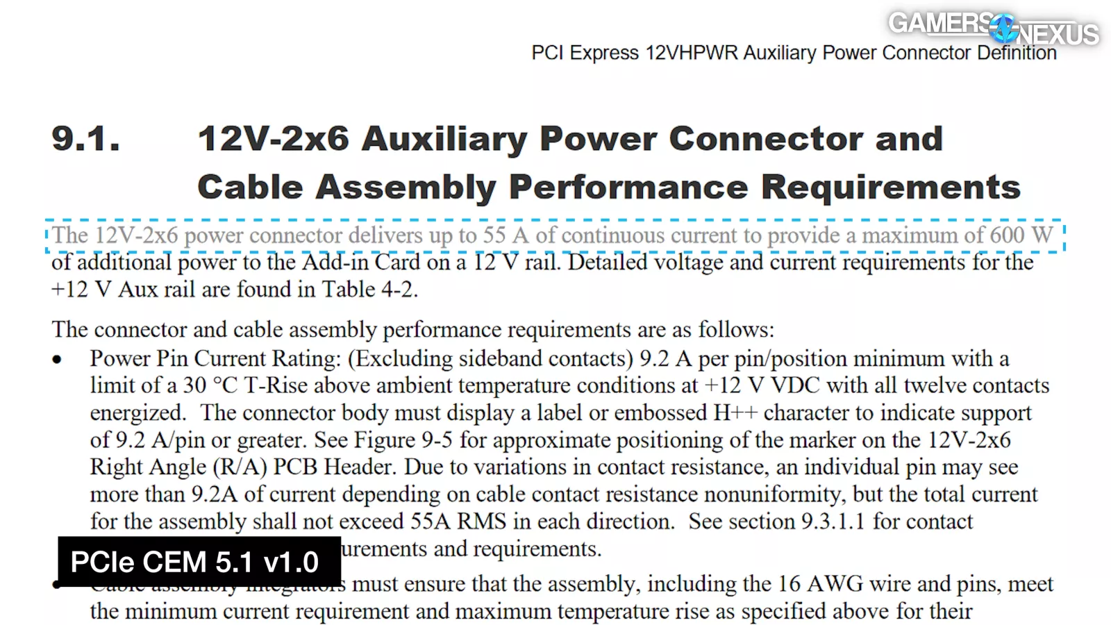
Loss as heat in a circuit can be calculated with the equation P = (I^2) * R, where P is the power lost, I is current, and R is resistance. Heat loss increases with both current and resistance. Current should theoretically have a flat limit across all pins, but as the CEM says, "due to variations in contact resistance, an individual pin may see more than 9.2A of current depending on cable contact resistance nonuniformity."
Larger normal forces (a tighter squeeze) and metal-on-metal wipe area means lower electrical resistance and lower heat, but it also makes it physically harder to seat the plug.
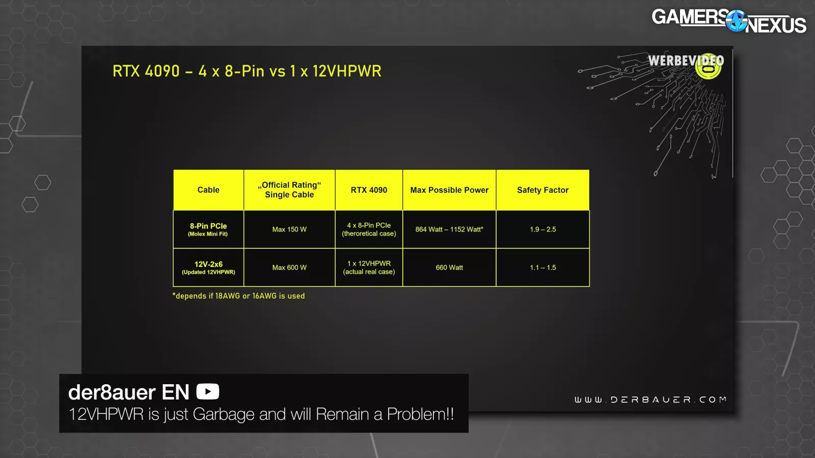
There are a few disadvantages to 12VHPWR versus PCIe 8-pin. PCIe 6/8-pin power connectors are comparatively big, and they slide into place easily and with a noticeable click. As several have pointed out, the 150W spec for 8-pin PCIe connectors is usually well below the rated maximum capacity, whereas 600W is closer to the rated capacity of 12VHPWR connectors, reducing the margin of safety.
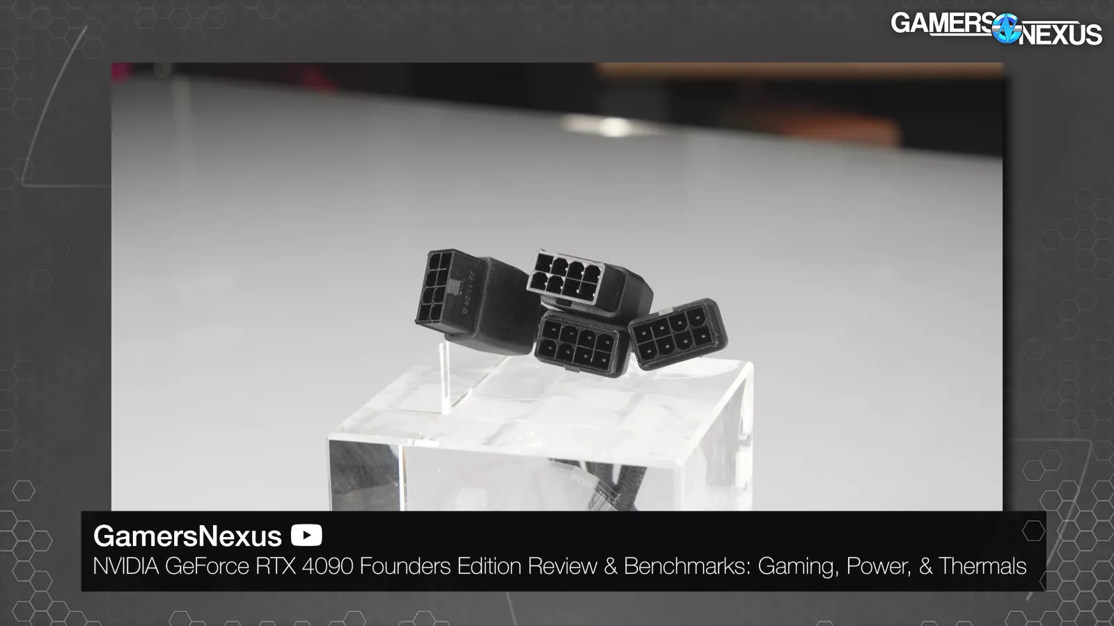
Providing 600W requires four big eight-pin connectors with 12x 12V wires, providing redundancy and spreading out heat, or a single 12VHPWR connector densely packed with only 6x 12V wires.
If one 12VHPWR pin heats up, it may soften the plastic housing and cause a cascading failure, especially on the cable side where the plastic is what holds the metal pieces in place.
Checking with der8auer on this concept of softening plastic housing and cascading failures, he noted: "If there is significant contact resistance on the connector side this could increase drastically to maybe 10W-20W. And 10W-20W on such a small part will heat up over time which can then cause the connector to melt or at least become soft in regard to the plastic. If the plastic becomes a little softer, an already slightly bent pin can bend even more. Again increasing the contact resistance and then leading to the failure."
Also, because of the tighter safety margin, factors like alloys, tolerances, structures, and contact areas all require more standardization and diligence from every random manufacturer.
A quick note here about the 30C threshold that appears in the specs. Seeing a connector rise 30C above the metal and air literally around the connector, NOT room ambient, is an indication that the connector can't keep up with heat dissipation, and could indicate the beginning of thermal runaway. It doesn't have to do with the safe temperature of the connector or the rated power delivery at a given temperature. It also doesn’t have to do with the greater room temperature, as those who worked on the spec told us. It is about the immediate ambient of the connector and what surrounds it directly.
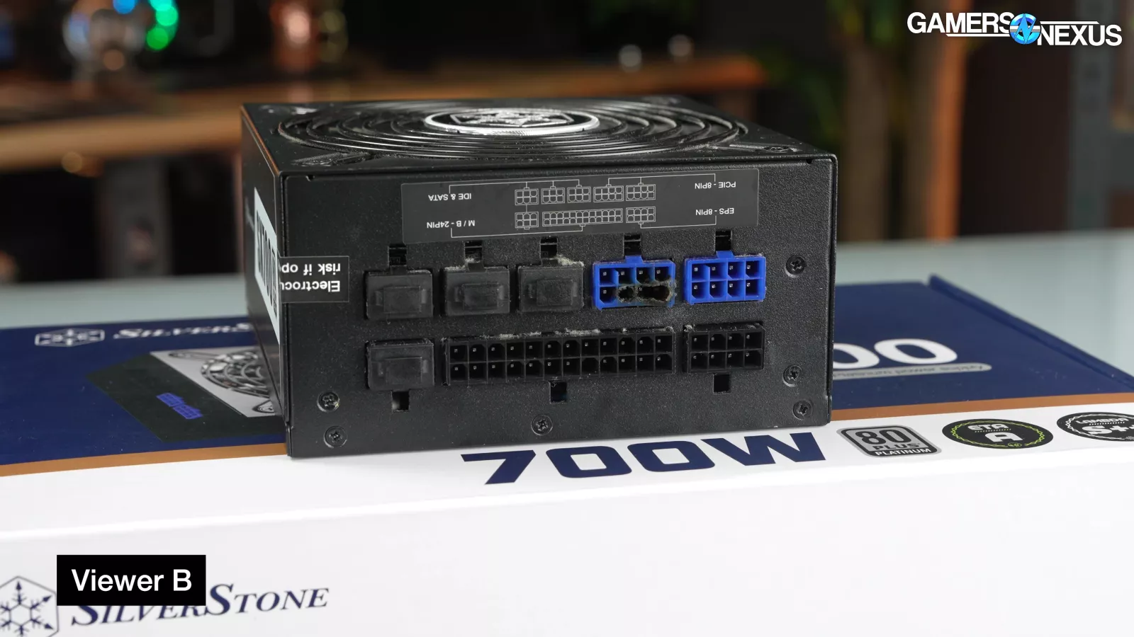
The older connectors can and do fail. As examples, we found the two most recent viewer emails we'd gotten about melted 8-pin PCIe cables and connectors and bought both PSUs and their associated cables.
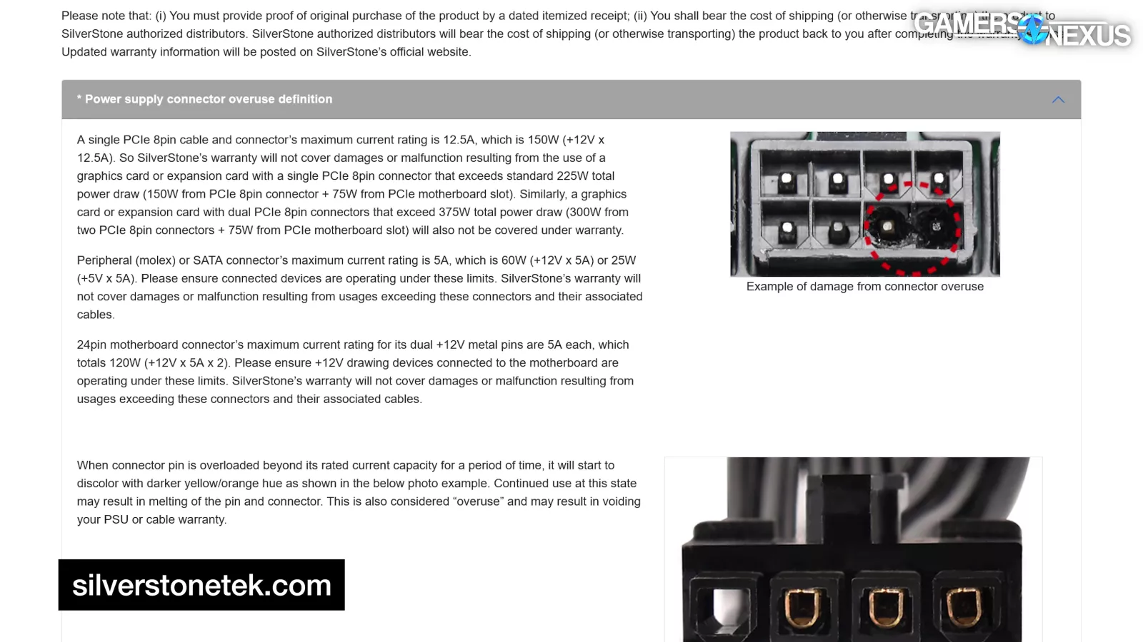
Both viewers had used stock daisy-chain PCIe connectors included with their PSUs to power 300W+ GPUs. SilverStone's warranty sheds some light on the issue: the company doesn't cover "connector overuse," which it defines as "damages or malfunction resulting from the use of a graphics card or expansion card with a single PCIe 8pin connector that exceeds standard 225W total power draw (150W from PCIe 8pin connector + 75W from PCIe motherboard slot). Similarly, a graphics card or expansion card with dual PCIe 8pin connectors that exceed 375W total power draw (300W from two PCIe 8pin connectors + 75W from PCIe motherboard slot) will also not be covered under warranty." Basically, using SilverStone's daisy-chain connectors almost always voids the warranty.
Edit: since the video accompanying this article was published, SilverStone stated to us that "The use of PCIe daisy chain cables included with our power supply does not void warranty if it was used in manner within the limit of our overuse definition. So technically we used an 8pin PCIe on our power supply’s modular interface, but that connector is capable of supporting 300W."
If you ever have a failed component, you can email [email protected] and let us know what the failure is. If it’s in the warranty window, that’s even better because then we can buy it from you and we can use it to test the manufacturer’s warranty.
Part 3: Why Does 12VHPWR Even Exist
This chapter covers why 12VHPWR even came to exist.
So, PCIe 8-pin connectors and cables are generally overbuilt, but not always, and not to a consistent standard - but because there is more room in the spec, it is more likely they are overbuilt even if accidentally. It's known that running more than 150W over an 8-pin PCIe cable can cause melting in edge cases, as shown by SilverStone's nicely illustrated warranty page. GPU power consumption requirements have increased, though, and they’re not really showing any signs of slowing down. To reliably get more than 450W of auxiliary power into cards in a small package required a new cable. The 12VHPWR connector is smaller, enables better cooling on the card by reducing PCB length and therefore enabling flow-through, reduces cable clutter, and allows for more flexibility in PCB design.
Full-size PCIe x16 devices can draw 75W of power through the PCIe slot. Modern GPUs require more than that, and for years that additional power has been delivered by 6- or 8-pin connectors.
Both styles of connector carry the same three 12V power lines, but 6-pin connectors are rated for 75W, while the extra two pins indicate a higher standard that can carry up to 150W.
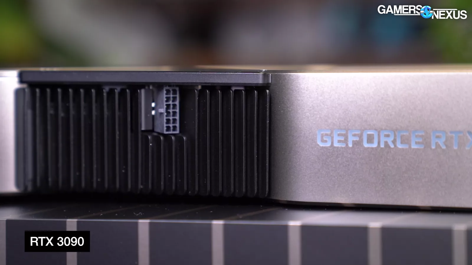
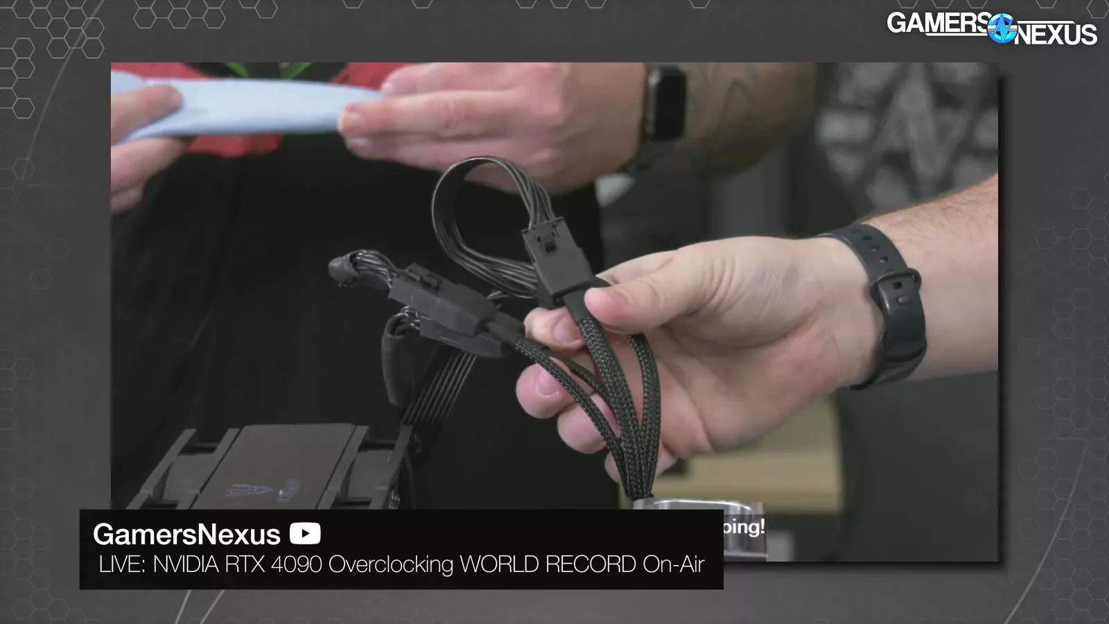
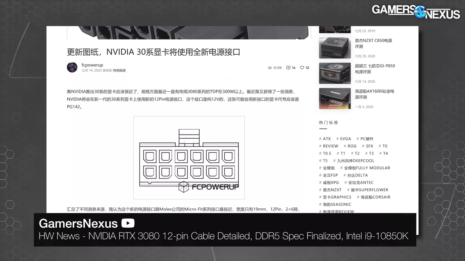
On September 17th 2020, the NVIDIA RTX 3000 Founder's Edition cards launched with a new 12-pin connector. It was a big change in form factor, but electrically nothing new: six 12V lines and six grounds numerically matched dual PCIe 8-pin connectors, which you can find in many other cards. Some dedicated power cables for these cards were released but, for the most part, everyone used the included adapter dongles. We're now aware that NVIDIA had been considering PCIe power replacements for years beforehand, some of them exotic, but the 12-pin design was an off-the-shelf part from Molex (like the old 8-pin connector). Behind the scenes, both 30 and 40 series went through multiple connector revisions before shipping—but we're getting ahead of ourselves.
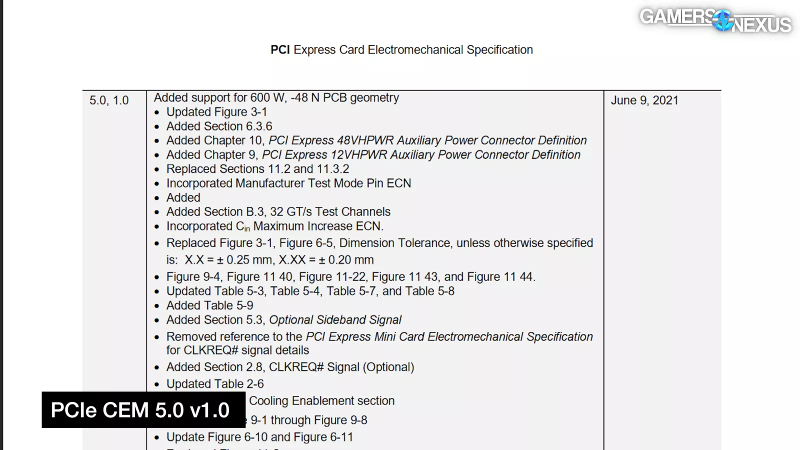
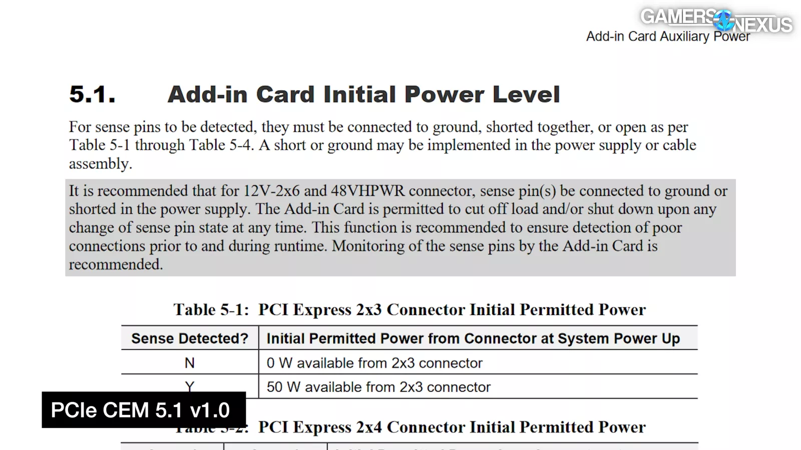
The Peripheral Component Interconnect Special Interest Group (or PCI-SIG)'s PCI Express Card Electromechanical Specification (PCIe CEM) Revision 5.0, Version 1.0 was released on June 9th 2021. This was the first time that the 16-pin 12VHPWR connector was officially defined, but there were no GPUs with 12VHPWR connectors.
Un-cynically, the 12VHPWR connector was smaller; therefore it obstructed airflow less, reduced cable clutter, and allowed for more flexibility in PCB design. Cynically, pushing for a new connector allowed NVIDIA to lead the industry and pull its competitor(s) along, like RTX and DLSS, and, to some extent, now AI.
The early 12-pin connector was a soft launch that predated the spec, and it lacked the four sideband connections that would be added to make 12VHPWR.
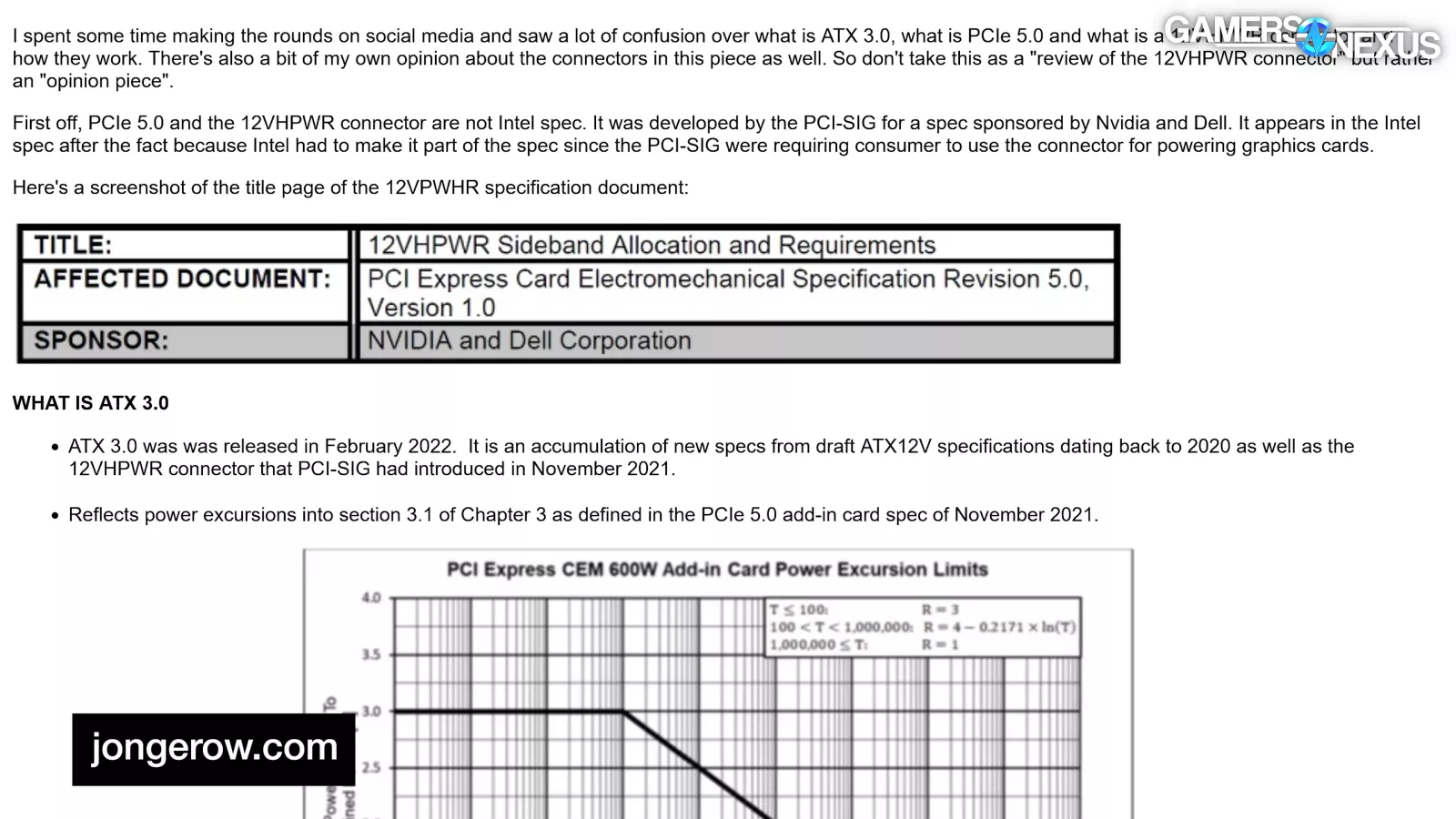
According to Jon Gerow, NVIDIA and Dell Corporation were listed as co-sponsors of the sideband addition. PCI-SIG is a consortium: NVIDIA is a member, as are Dell, Intel, AMD, and dozens of others. To paraphrase an insider that we spoke to: there was no reason to think that adding four signal pins to a tried-and-true design would cause any problems.
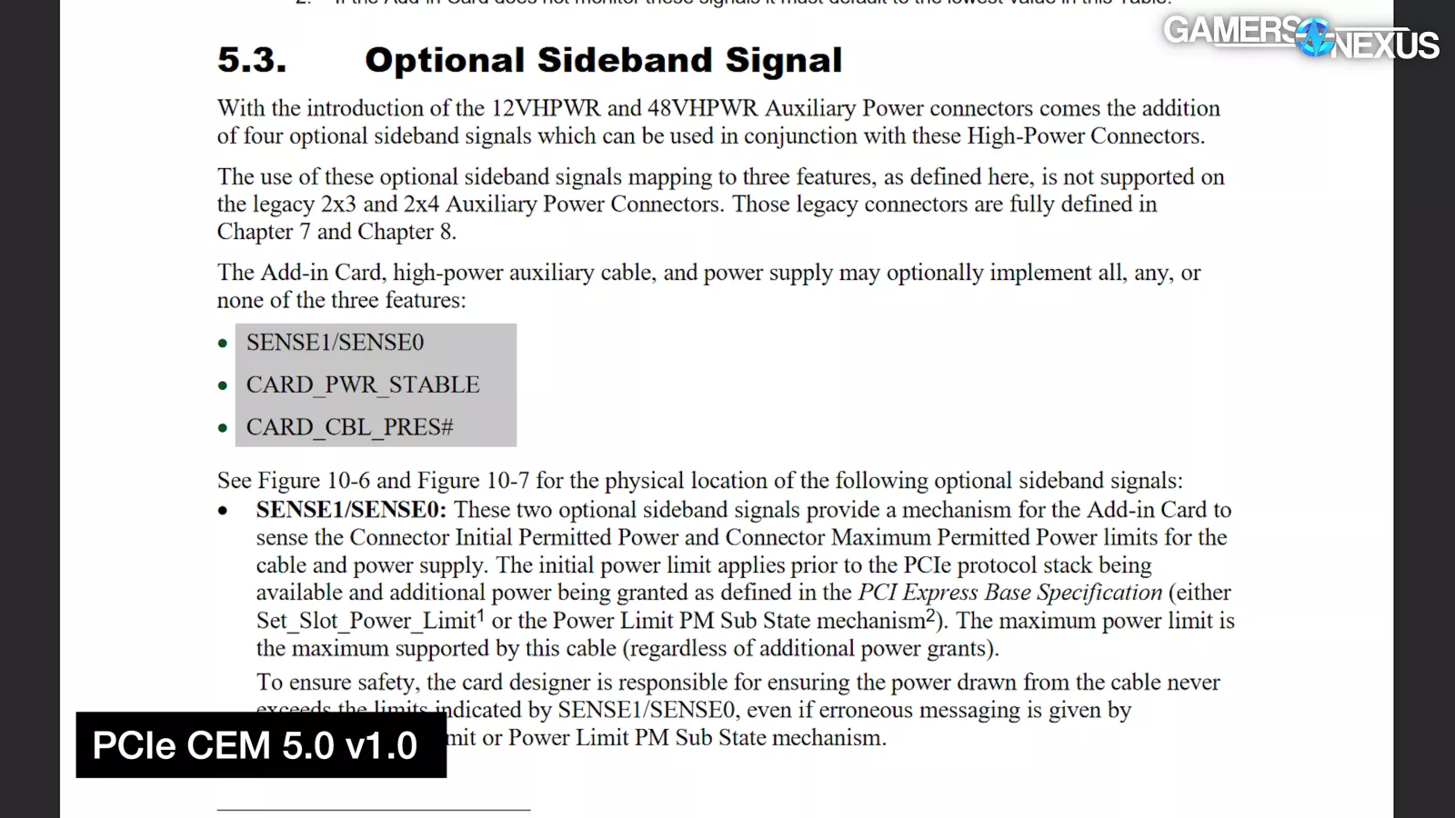
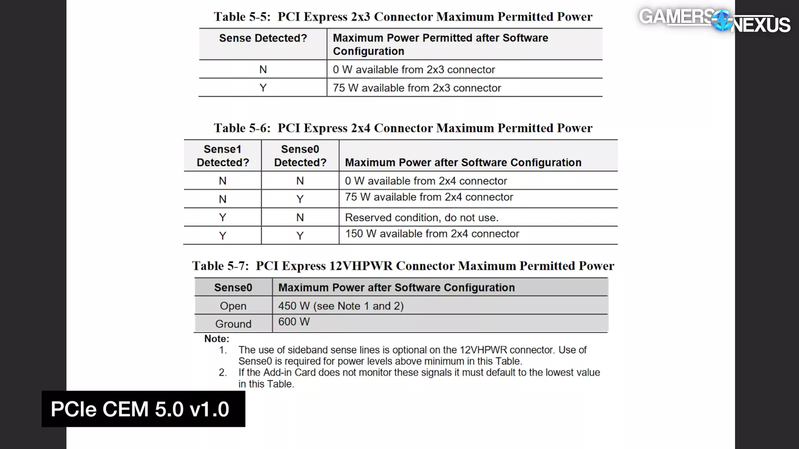
The four sideband pins were SENSE0/SENSE1, CARD_PWR_STABLE, and CARD_CBL_PRES#. At this point, the PCIe CEM said that "the Add-in Card, high-power auxiliary cable, and power supply may optionally implement all, any, or none of the three features." CARD_PWR_STABLE and CARD_CABLE_PRES# were data signals that were intended for enterprise, Sense1 was unused, and Sense0 signaled whether 450W or 600W was available. Grounding Sense0 meant 600W; opening Sense0 meant 450W.
One troubling thing that you may not have known is that there’s really no required validation process for this stuff. A manufacturer could feasibly do whatever they want without actually ensuring that the cable can meet these various loads. Even though PCI-SIG sets the specification, it doesn't step in and validate and stamp cables. It’s not part of the scope of what PCI-SIG does as it’s up to the manufacturers to police themselves. They could also do whatever they wanted with PCIe 6/8-pin, it’s just that there’s more overhead there and the cable has been refined over decades.
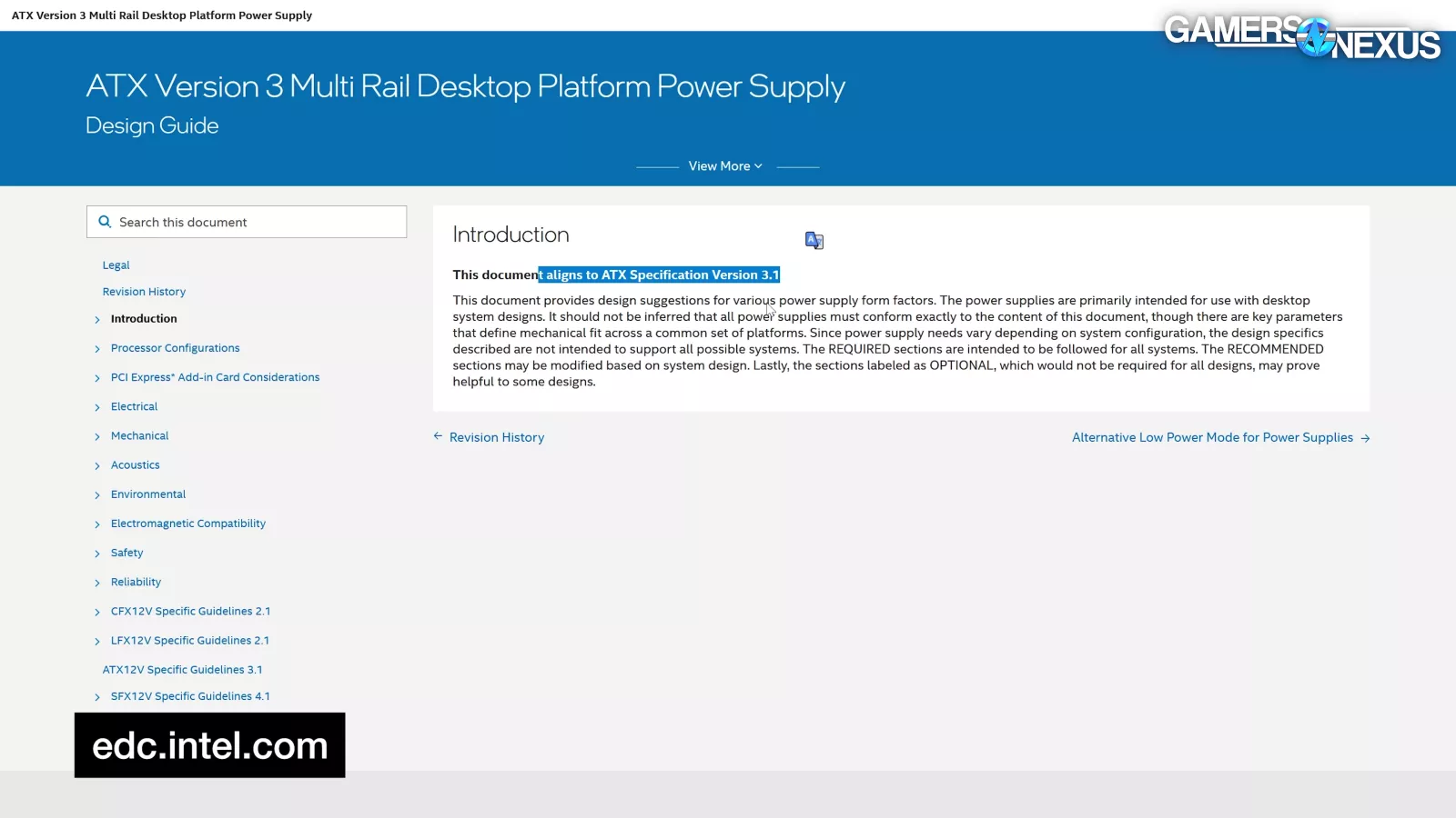
The ATX Version 3.0 Multi Rail Desktop Platform Power Supply Design Guide Revision 2.0 was finalized on February 1st, 2022. Revision 2.0 was the first release of ATX 3.0 and, as of today, it's up to ATX Version 3.1 Revision 2.1a. As you may have guessed based on that mess of a name, Intel curates the ATX spec, but it's really a collaborative set of guidelines to keep hardware compatible. Intel does some voluntary validation, and third parties like Cybenetics do more, but the spec wasn't and isn't law. The first release focused heavily on power excursions, which were a huge concern at the time from the RTX 30 series’ massive transients, but it also included the as-of-yet-unused 12VHPWR connector, which was marked as "Required for PSU > 450 Watts."
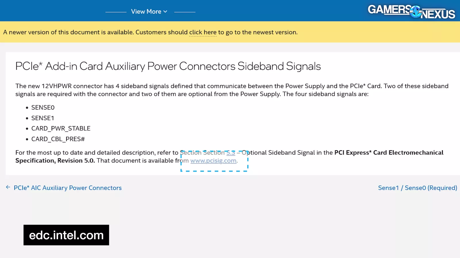
The 12VHPWR section referred readers to PCI-SIG for details.
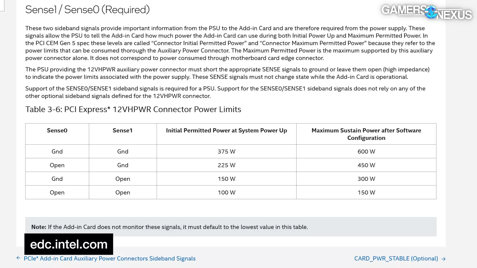
Most importantly, this release included updates to the two sense pins. According to the ATX 3.0 spec, PSUs with native 12VHPWR were required to support both sense pins and use them to signal whether the PSU itself could deliver a given wattage. The four possible open/ground combinations of the two pins were used to signal four sustained power tiers, not two: 150W, 300W, 450W, and 600W. Leaving both pins open signaled the lowest power capability of 150W, and "if the Add-In-Card does not monitor these signals, it must default to the lowest value in this table [150W]." This conflicted with the PCIe CEM: the sense pins were required on the PSU side, and the GPU was required to monitor them.
In March 2022, the ATX12VO 2.0 spec came out. It was released only a couple of weeks after the ATX 3.0 spec, but it already included a mechanical change to the connector to protect the sideband wires. This change wouldn't be reflected in the PCIe CEM for months, and it would take even longer for manufacturers to catch up.
Part 4: The Launch
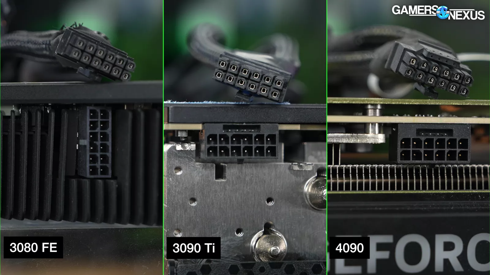
Immediately afterwards, on March 29th 2022, the RTX 3090 Ti (watch our review) launched. This was the first card that used a 16-pin 12VHPWR connector, but the adapter cables that shipped with these cards were the existing 12-pin style. Connectors were keyed so that 12VHPWR plugs could fit into any 30-series card, but 12-pin plugs couldn't fit into any 12VHPWR sockets except for the 3090 Ti's. Like we said: It was a mess from the start. The 3090 Ti was functionally a test platform for the upcoming 40 series. The 3090 Ti didn't comply with the Intel spec from February of that year before it, which stated that leaving both sense pins open should actually signal 150W, not 450W.
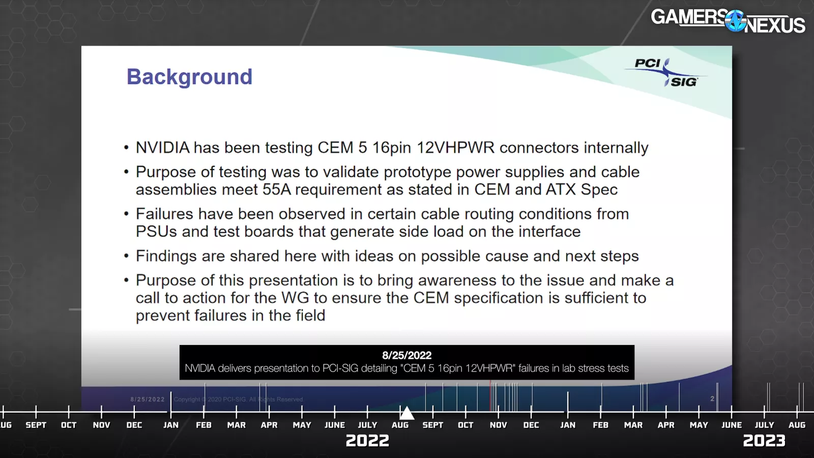
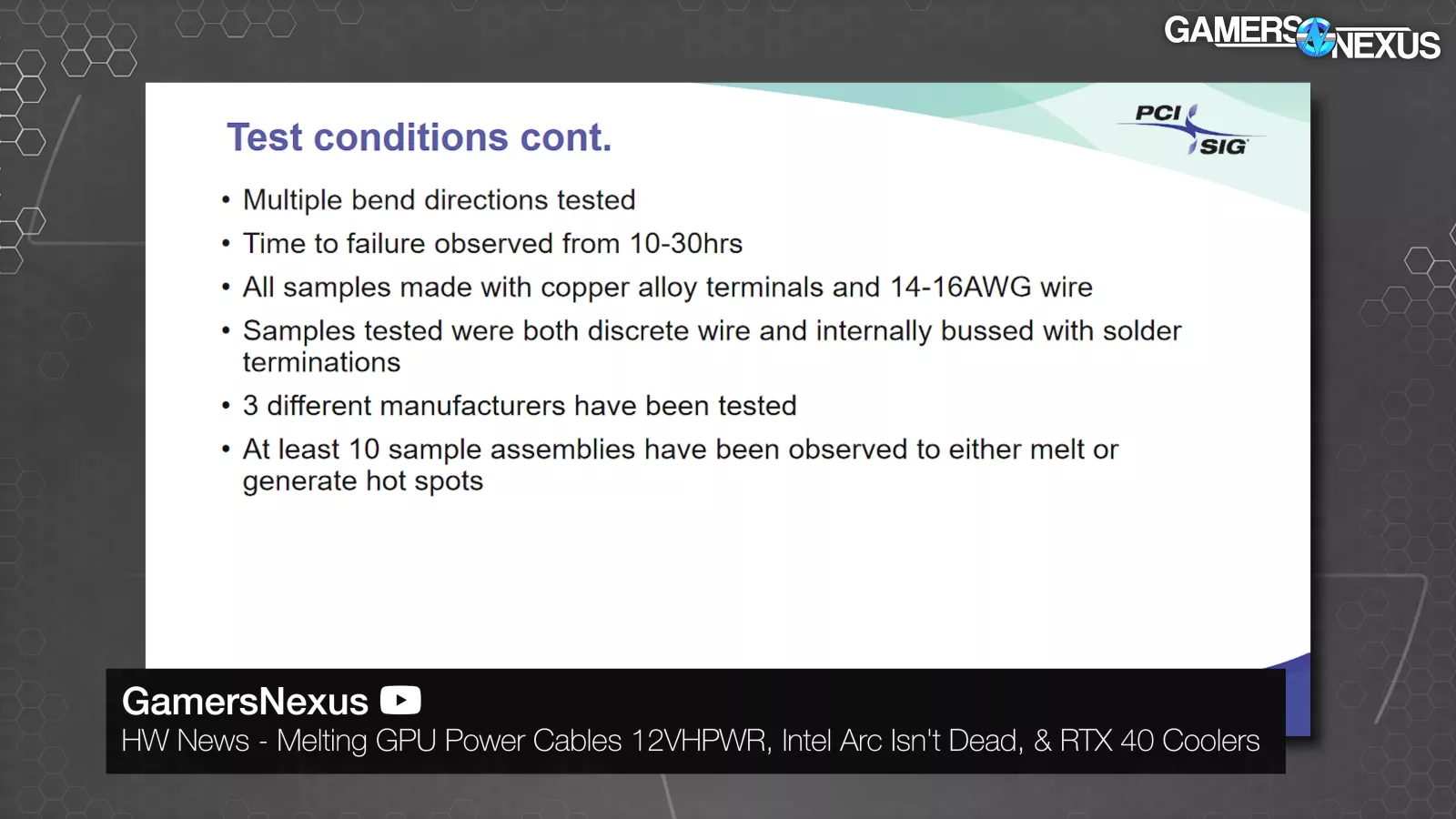
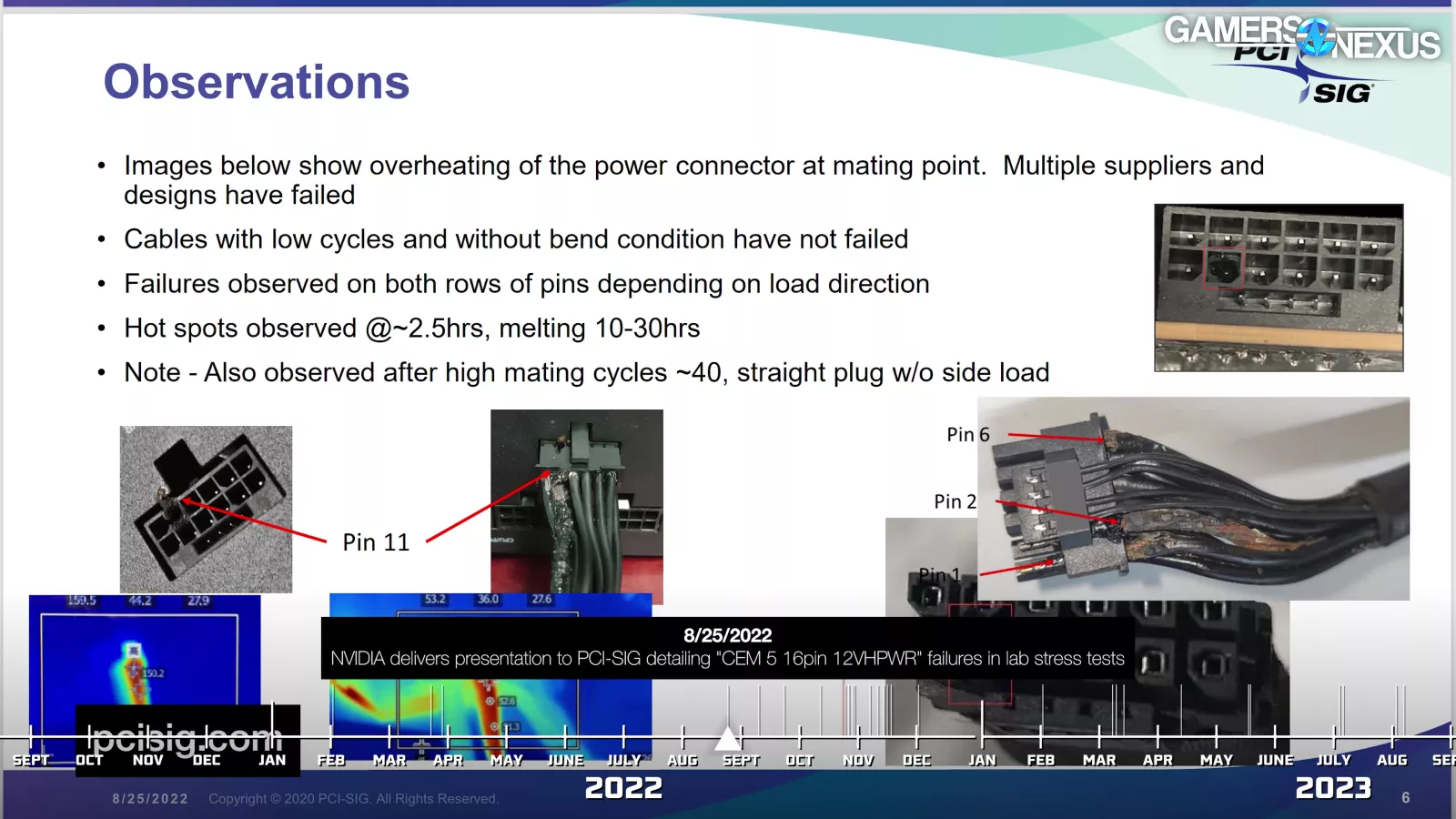
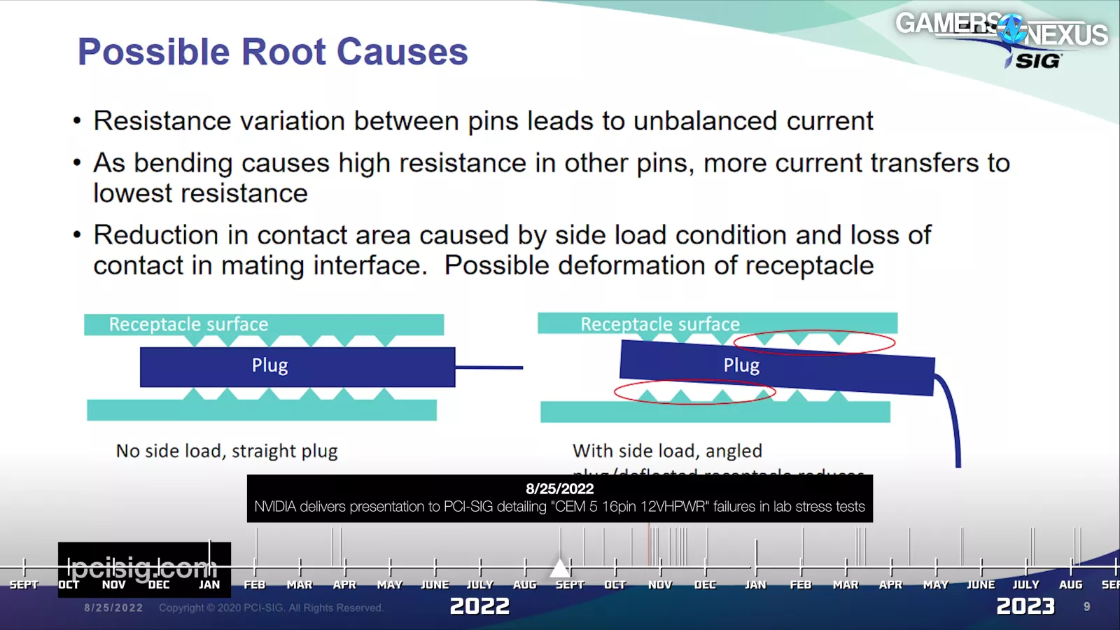
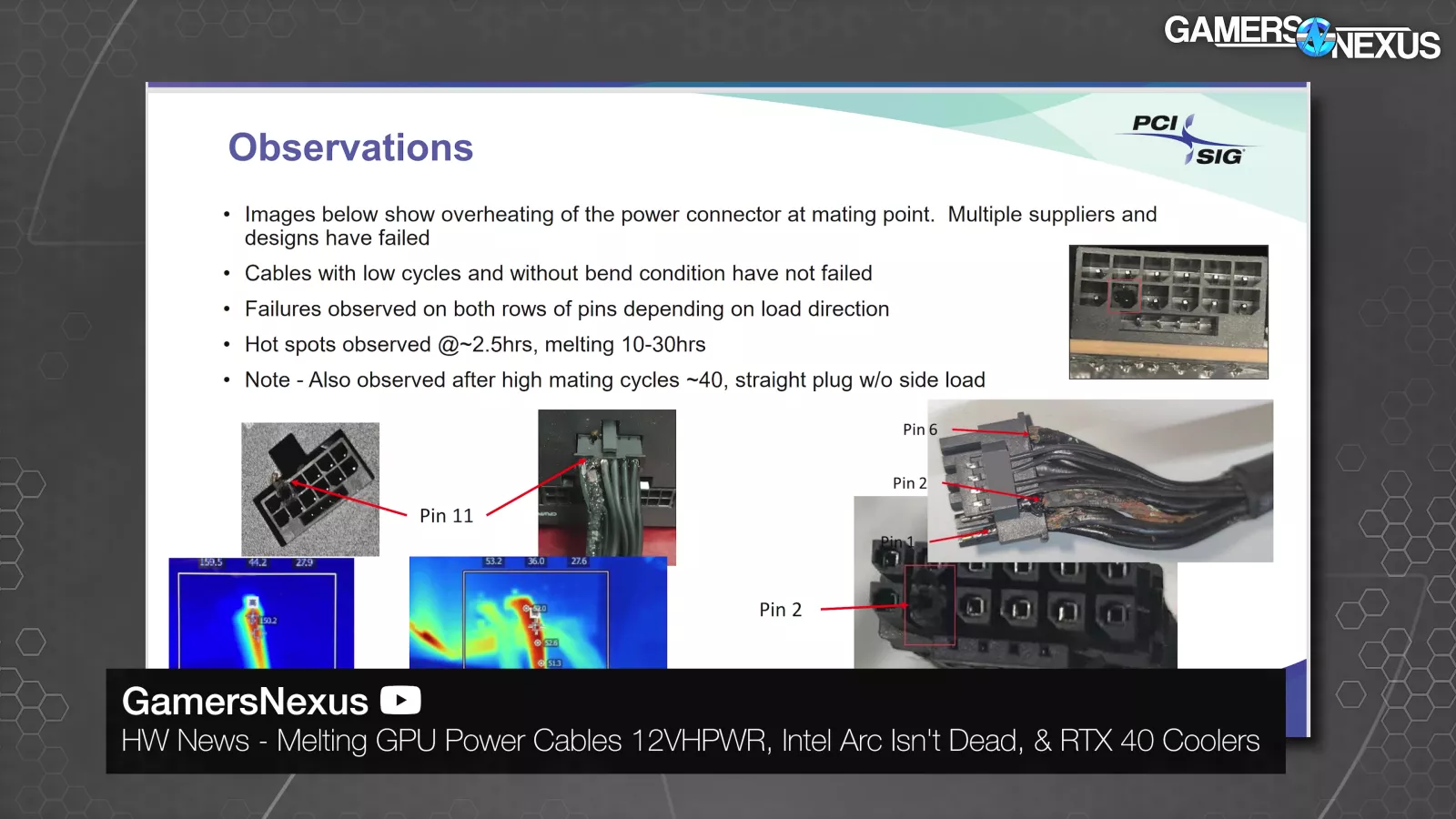
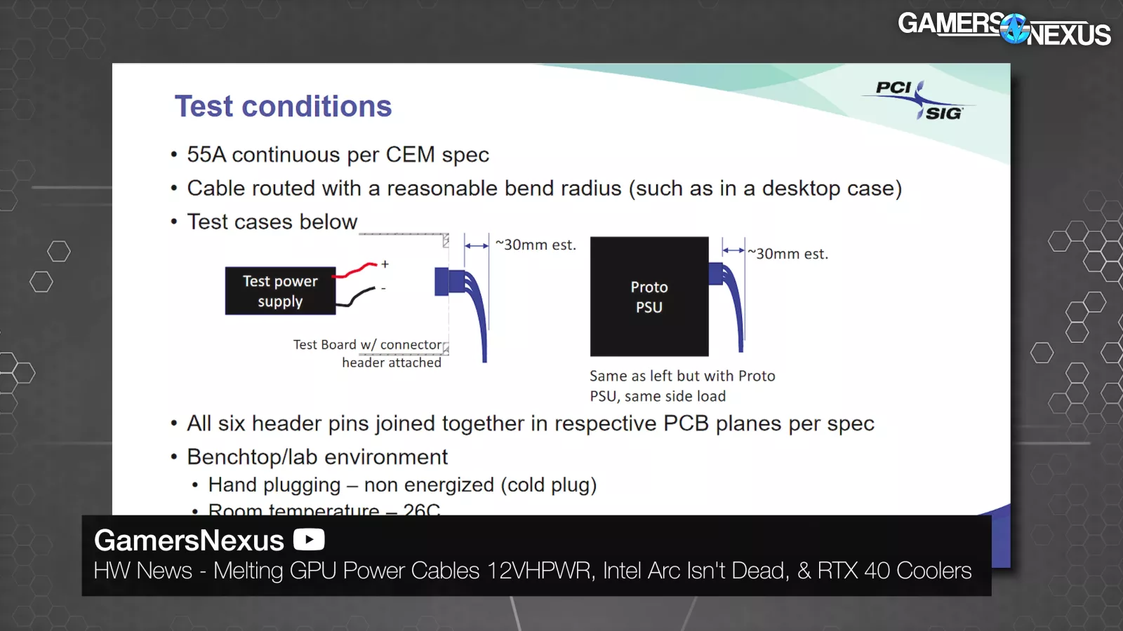
On August 25th 2022, it began. PCI-SIG showed a grim internal presentation from NVIDIA about "CEM 5 16pin 12VHPWR." "Failures have been observed [in testing] in certain cable routing conditions from PSUs and test boards that generate side load on the interface." This was a "call to action for the WG to ensure the CEM specification is sufficient to prevent failures in the field. [...] Time to failure observed from 10-30hrs. All samples made with copper alloy terminals and 14-16AWG wire. Samples tested were both discrete wire and internally bussed with solder terminations. 3 different manufacturers have been tested. At least 10 sample assemblies have been observed to either melt or generate hot spots."
The cables shown in this presentation were real 16-pin 12VHPWR cables, which were still rare in the wild as no GPUs required them.
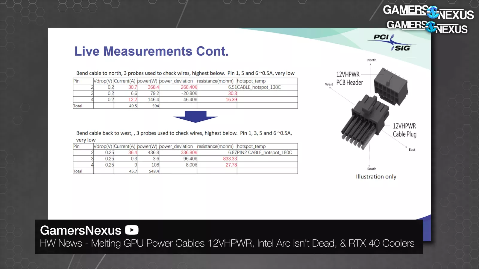
NVIDIA tested non-adapter cables, it tested 14AWG cables, it tested both discrete wires and a soldered bus, and it tested multiple manufacturers. The implied conclusion was that none of it mattered. These tests were mostly concerned with bending and sideloading under high load.
This was the source of the bend radius recommendations still seen now.
On September 10th, Wccftech leaked an email that had been sent to PCI-SIG members in the wake of that presentation, which stated that "PCI-SIG has become aware that some implementations of the 12VHPWR connectors and assemblies have demonstrated thermal variance, which could result in safety issues under certain conditions" and "we recommend members work closely with their connector vendors and exercise due diligence in using high-power connections, particularly where safety concerns may exist."
Wccftech ran this under the headline "PCI-SIG Warns of Potential Overcurrent/Overpower Risk With 12VHPWR Connectors Using Non-ATX 3.0 PSU & Gen 5 Adapter Plugs."
Neither "Non-ATX 3.0 PSUs" nor "Gen 5 Adapter Plugs" were mentioned by PCI-SIG in that memo -- that was inserted by Wccftech. We have no idea why Wccftech ran with that headline, but for months after this reporting, the conversation would revolve around adapter cables specifically.
For NVIDIA, this was nightmarish timing with 40 series on the horizon.
As more outlets reported on the story, NVIDIA emailed JayzTwoCents to say that "I think you're worrying about issues that don't exist. We have thoroughly tested our power adapters and expect no issues. Potential customers who are concerned can use the RTX 40 Series connector solution with confidence."
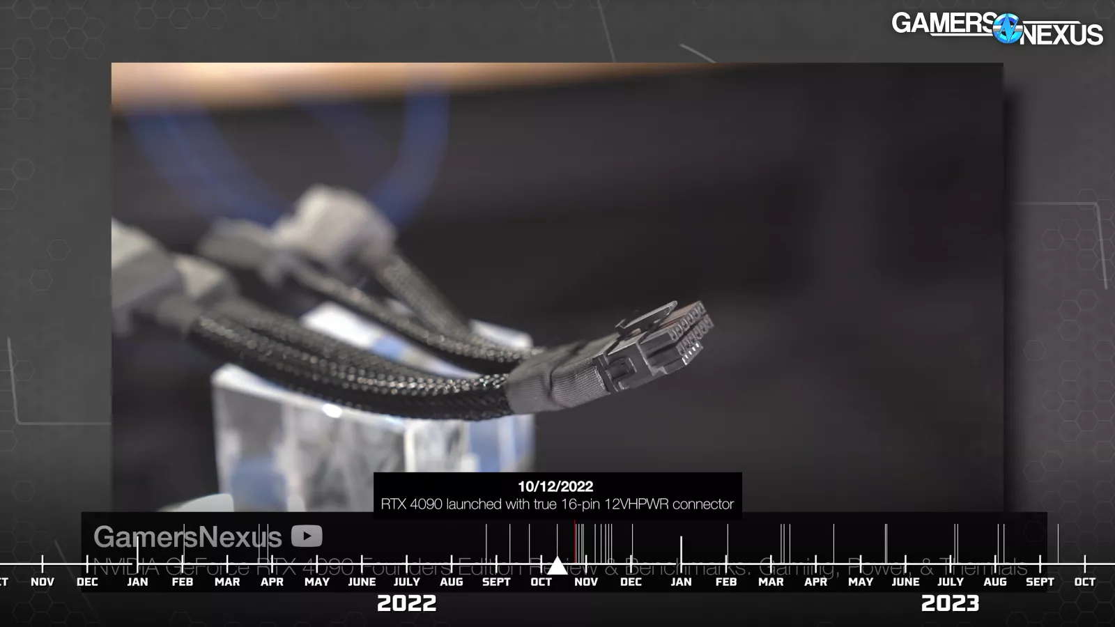
On October 12th 2022, the RTX 4090 (beware of scalped prices) launched. This was the first time a true 16-pin 12VHPWR connector was required, but all cards shipped with adapter dongles. NVIDIA's adapters were able to “intelligently” ground or open sense pins based on how many 8-pin cables were connected. This meant that, as we saw in our review, connecting just 3 of the 4 cables would reduce the overpower provisioning permitted through overclocking software at the time.
The 4090 (watch our review) launched alone for its first month, so at first, all 12VHPWR problems occurred with 4090s because that’s all there was.
Part 5: The Melting
Less than two weeks later, on October 24th, the first report of a burned-out adapter hit Reddit. By the 25th, there were two, and NVIDIA confirmed to The Verge that it was "investigating the reports."
Starting on the 27th, igor'sLAB took the wheel with a rapidfire series of articles, starting with the headline, "The horror has a face – NVIDIA’s hot 12VHPWR adapter for the GeForce RTX 4090 with a built-in breaking point." At this point, Igor operated under the assumption that "it’s the adapter solution exclusively provided by NVIDIA to all board partners, which has fire-dangerous flaws in its inner construction!" and "the native 12VHPWR cables of the better power supplies show that it can be done differently." He speculated that the solder bus within the adapters was fragile and inadequate, and that if any connections were to break, "the inner bridge between the pins is too thin (resulting cross section) to compensate the current flow on two or three instead of four connected 12V lines." He assigned blame to Astron, a vendor for the connectors, and claimed that crimping rather than soldering would fix the issue.
On the 30th, we published the start of our first-party investigation of the issue. We tested adapters with many combinations of broken solder, cut cables, and overclocked GPUs, but didn't come close to melting anything. Our conclusion was that although failures were clearly happening, it wasn't due to inadequacy of the bus bar on at least our units, and we requested melted cables from viewers for further investigation.
Speculation about the solder joints and bus bars slowed down at this point, and redirected towards the contact design of the adapters.
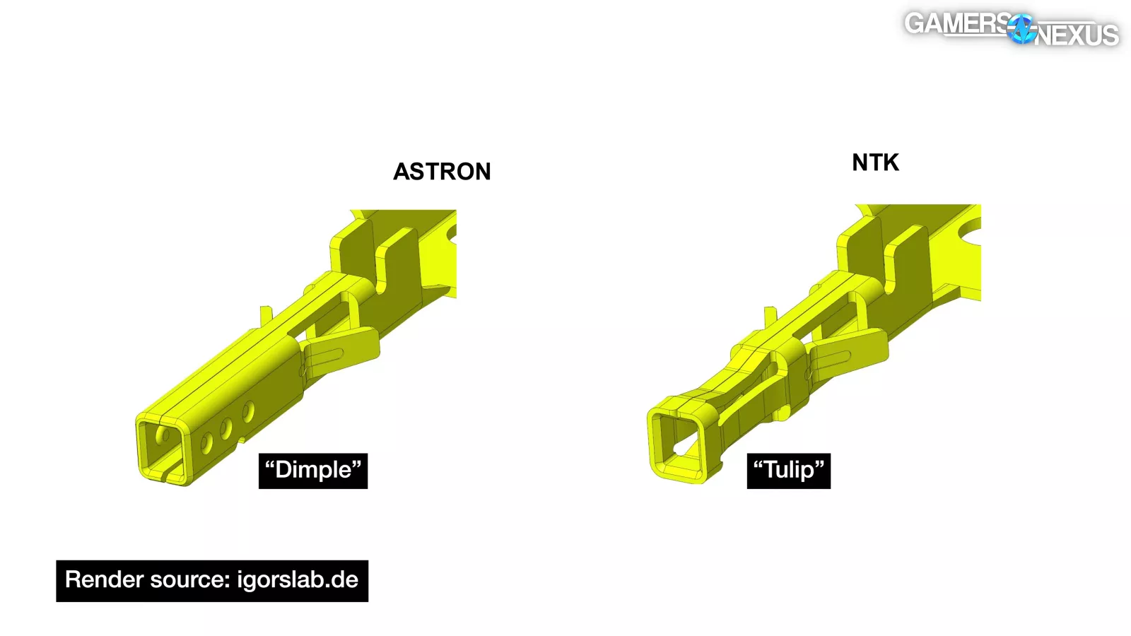
The design used in NVIDIA's Astron-manufactured adapters would be termed "3 dimple," versus the supposedly superior "4 spring" design from NTK and subcontractor 3con. Theories were being created and discarded almost literally hour-by-hour at times, so we went dark as we gathered information.
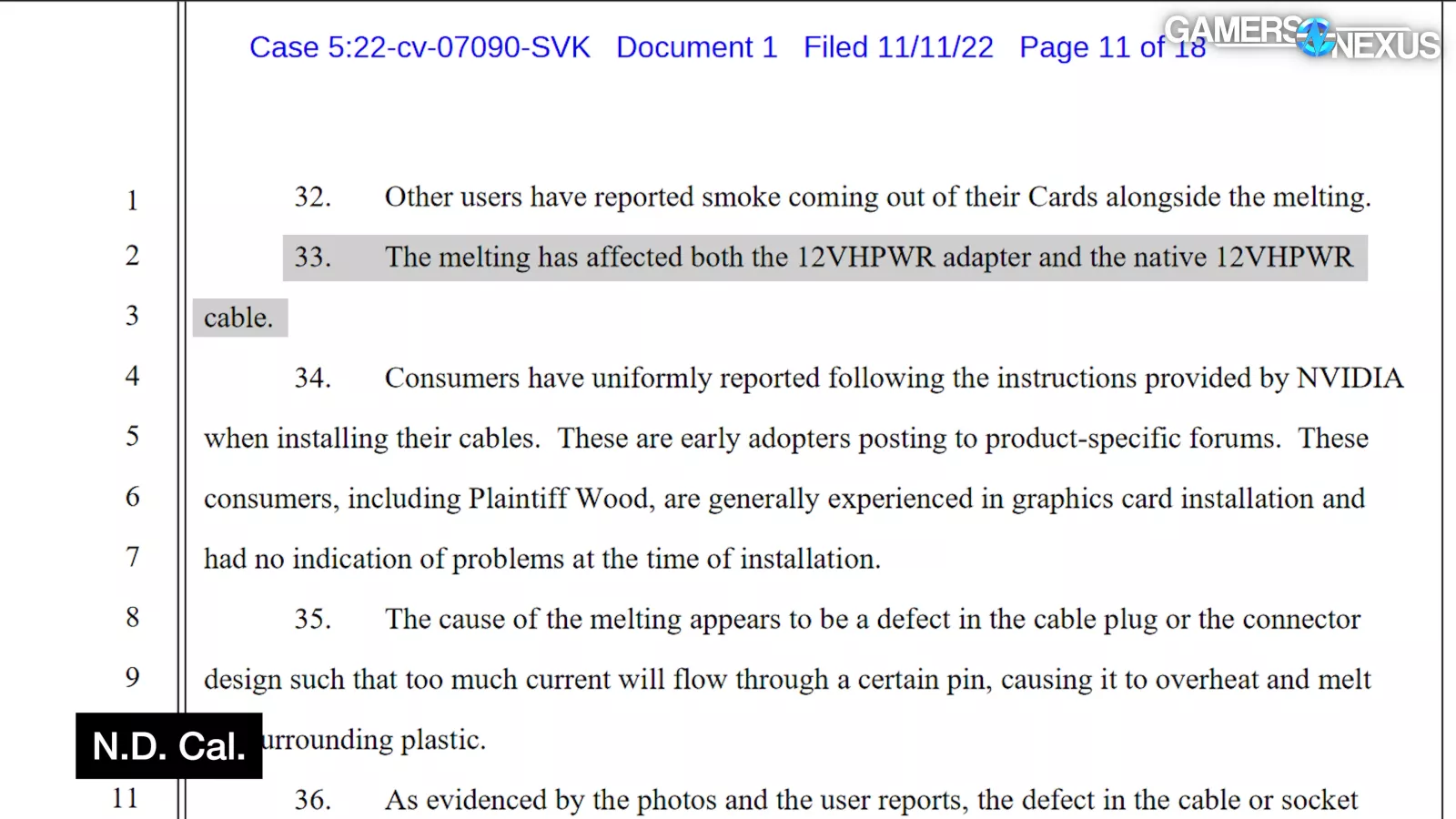
On November 11th, a complaint was filed with the goal of starting a class action suit against NVIDIA, filed in the Northern District of California by New York resident Lucas Genova, largely leveraging New York laws. Genova v. NVIDIA Corporation stated that "the melting has affected both the 12VHPWR adapter and the native 12VHPWR cable," and claimed that 23 reports of melting had been posted on r/nvidia on Reddit by the 7th, just two weeks after the first report.
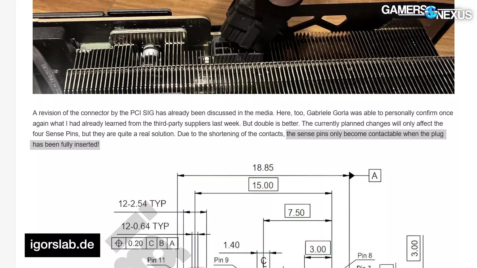
By November 14th, multiple outlets had misreported a mechanical change as “new” that had actually been in the public ATX12VO spec since March. NVIDIA separately confirmed a real change to Igor, though: that the sideband connections would be shortened so that "the sense pins only become contactable when the plug has been fully inserted."
That's called foreshadowing.
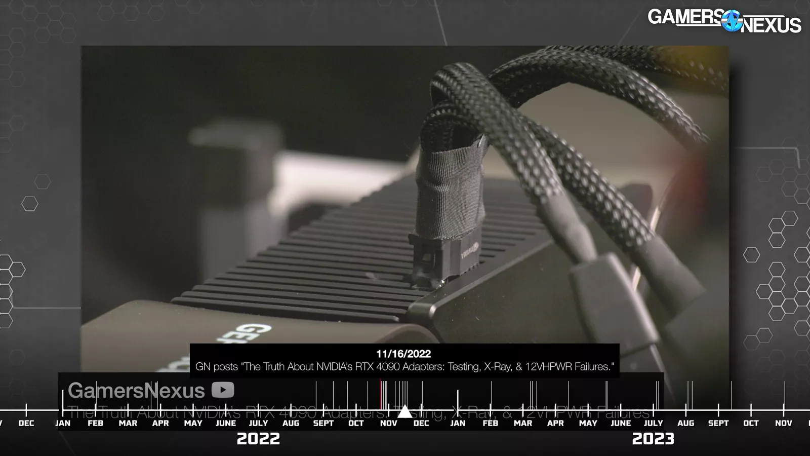
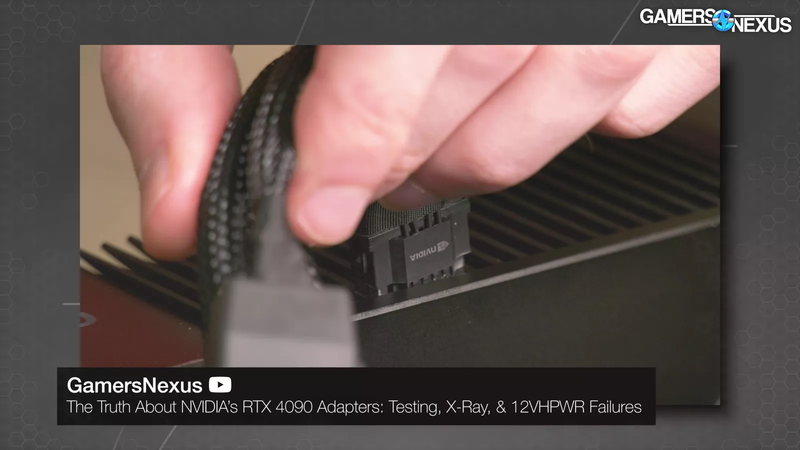
On November 16th, we melted a connector. Actually, we got pretty good at melting them
—if you've never seen that video, it's worth a watch for at least the reaction.
To start, we worked with Buildzoid to eliminate popular theories.
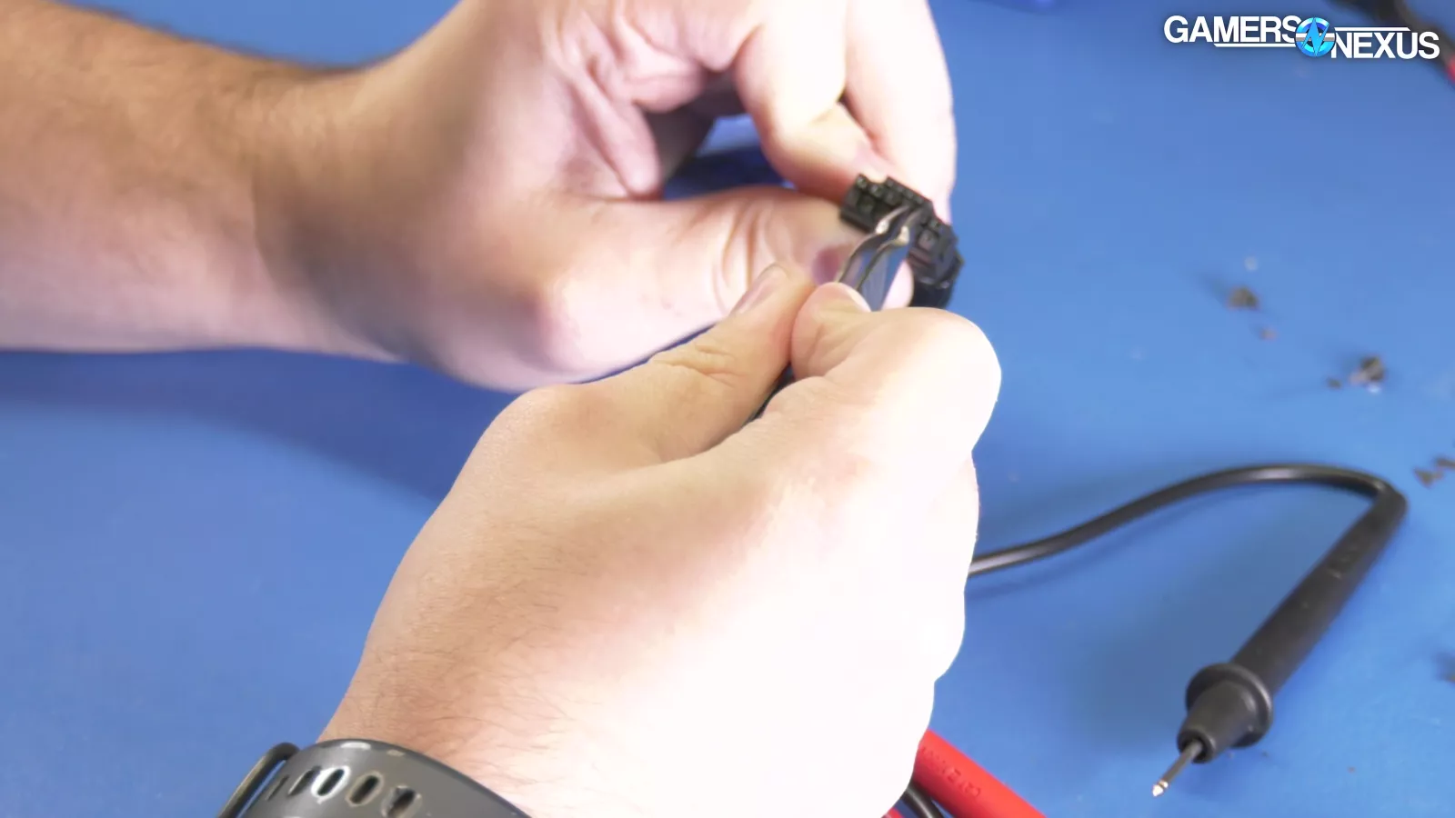
We manually spread the split terminals in an Astron adapter as far apart as possible, but saw no significant change. We cut four 12V terminals off of an adapter and ran a 600W load through the two remaining pins, but still saw no significant change.
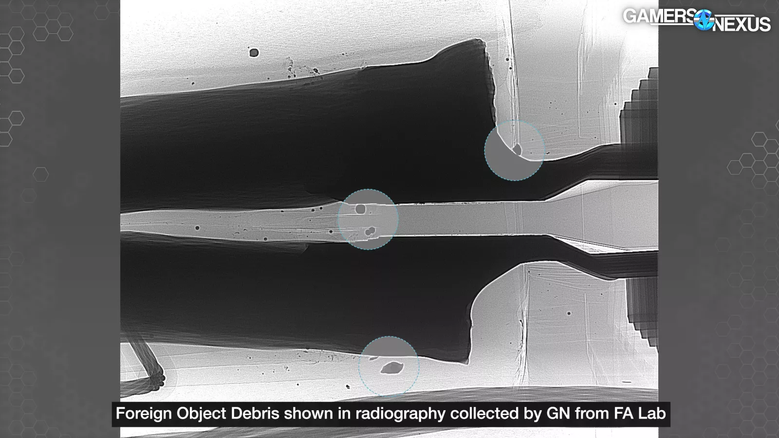
We then sent several viewers' failed adapters to a failure analysis lab, which found debris molded into the housing (called “Foreign Object Debris”), metal burrs on the terminals, and scraped-off plating. These were all problems, and similar problems may have led to some adapters melting, but they didn't melt ours.
Most of the failures known to us up to this point happened with partially inserted connectors, which is what we were able to replicate twice in one night.
We're aware that this doesn't account for every single melted connector. We want to be as clear as possible here, because we used the phrase "user error" a lot. To quote ourselves, "even if it is user error, at some point it's like, if the design is so bad that it encourages user error with any amount of regularity, then it is a combination of user error plus design error."
“Improper insertion” may be softer phrasing for the same concept: Our conclusion was that it was a mix of bad design of a new standard, and of improper insertion caused by both of these. The lack of additional power headroom means lower tolerance, plus the stricter requirement for quality metals and highly-rated plastics means that corner-cutting manufacturers wouldn’t be able to cut the same corners with the same success as with PCIe 6/8-pin.
The tight 12VHPWR connector with its four additional sideband connections and no tactile click, hidden deep inside the shroud of a gigantic 4090, could easily be left partially unplugged.
We found specifically that not fully seating the connector and then pulling it to the side would reliably melt it, and we also clearly identified markings on some adapters that indicated that they melted while partially inserted. To quote ourselves again, "most likely, it starts out as acceptable but incorrect, and accidentally gets tugged to be meltable."
This isn't a get-out-of-jail free card for manufacturers to do blanket RMA denials. In fact, there was a leak that NVIDIA allegedly told manufacturers to just approve all of those related RMAs.
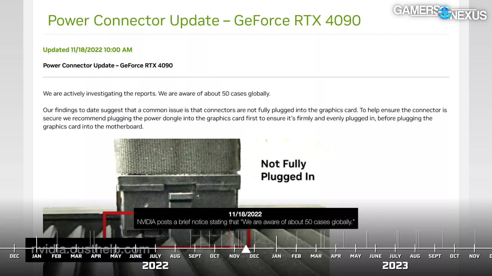
Immediately following our video, NVIDIA posted a statement that "we are aware of about 50 cases globally" and "our findings to date suggest that a common issue is that connectors are not fully plugged into the graphics card."
Based on this, there was a 0.04%-0.05% failure rate relative to approximately 125,000 RTX 4090s sold in the first month.
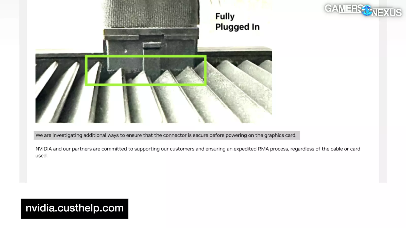
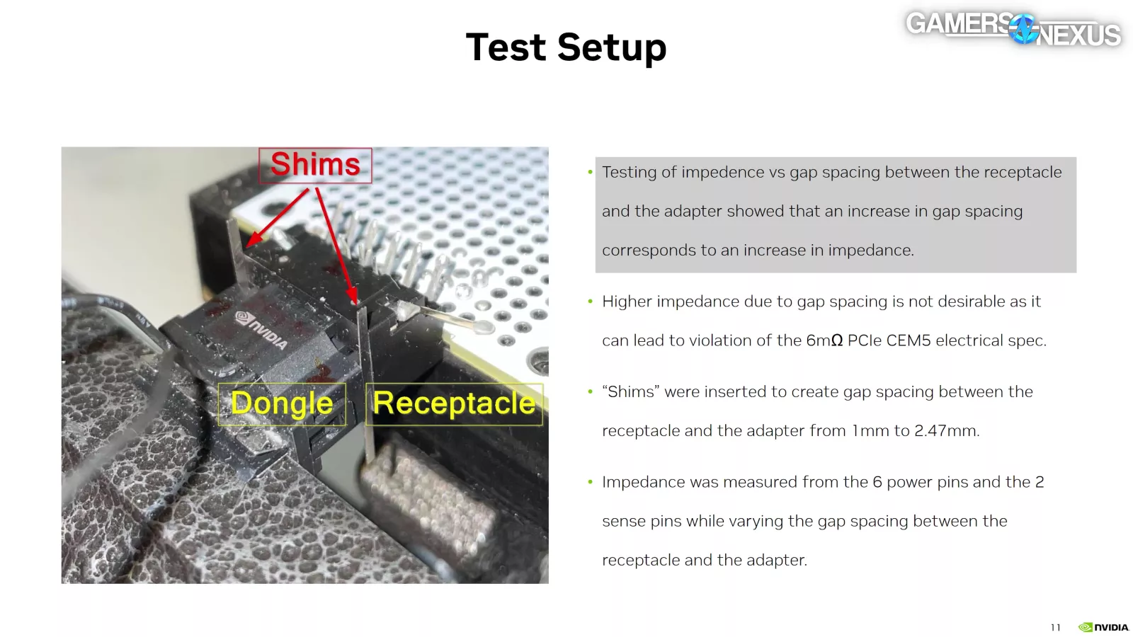
Also, NVIDIA stated that "we are investigating additional ways to ensure that the connector is secure before powering on the graphics card." As NVIDIA stated in an internal document afterwards, "testing of impedance vs gap spacing between the receptacle and the adapter showed that an increase in gap spacing corresponds to an increase in impedance" and "the impedance increases significantly after 1.5mm of gap spacing, and some pins violate the 6mΩ PCIe CEM5 electrical spec."
After this, things slowed down. In December, PCI-SIG sent an email to members saying that "when implementing a PCI-SIG specification, Members are responsible for the design, manufacturing, and testing, including safety testing, of their products," but it's unclear to us whether that was directed from or at NVIDIA.
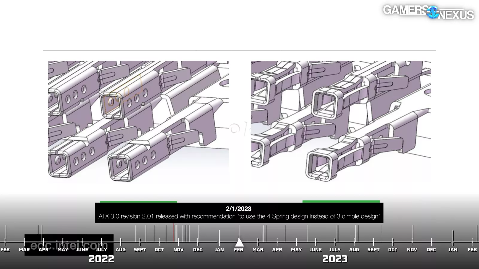
In February, months after we melted a 4 spring connector, ATX 3.0 revision 2.01 stated that "crimp contacts inside of the cable plug are recommended to use the 4 Spring design instead of 3 dimple design [...] which will increase the contact area for electrical current flow inside the 12VHPWR connector and reduce the temperature rise of each contact."
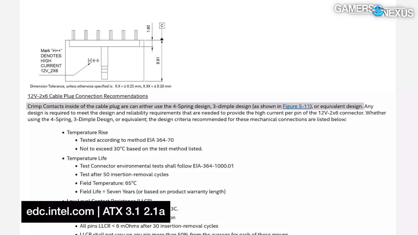
This statement was later altered, and today reads "Crimp Contacts inside of the cable plug are can [sic] either use the 4-Spring design, 3-dimple design [...] or equivalent design." Without any explanation we could find, they removed the text about increasing the contact area for electrical flow and for temperature reduction.
In March, Genova v. NVIDIA was voluntarily dismissed with prejudice by Genova, meaning it can’t be brought back to court. A reason was never officially disclosed. It is possible it was due to a personal settlement, but there is no evidence of this at this time. We don’t know why it was dismissed.
Part 6: The Melting, CableMod Edition
That brings us to Part 6: The Melting, CableMod Edition.
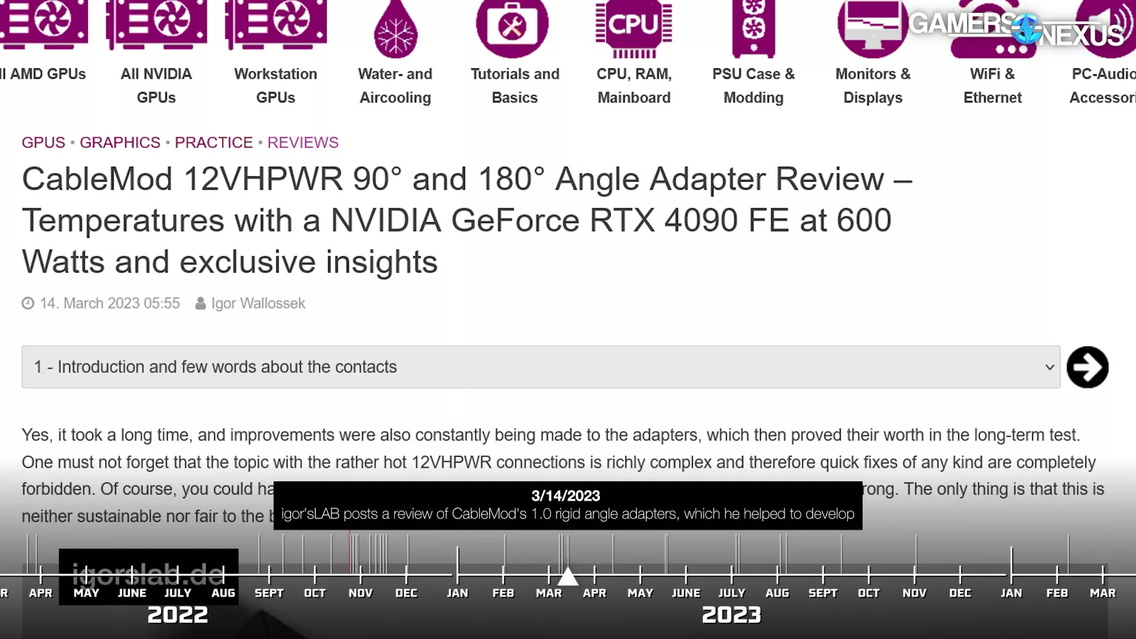
During all the fuss over adapter cables, bend radii, and toasted GPUs, CableMod consulted with Igor from igor´sLAB to develop rigid 90-degree and 180-degree adapters, with the final form revealed by Igor in March of 2023 and on sale by the end of the month.
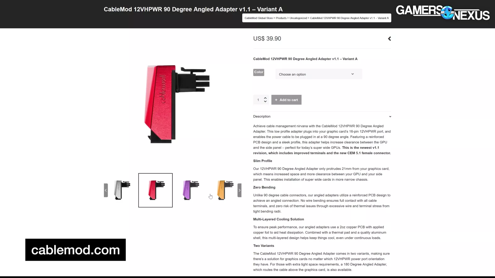
These were small PCB-based extensions (not really adapters) designed to enable a sharp bend away from the GPU. This was pitched as a safety feature, not just a cosmetic one, since it had been known for nearly a year that 12VHPWR cables could not be safely bent or pulled at sharp angles. CableMod wrote: "No wire bending ensures full contact with all cable terminals, and zero risk of thermal issues through excessive wire and terminal stress from tight bending radii."
These adapters incorporated what were supposed to be several improvements based on the ongoing controversy. They used 4-spring NTK contacts as recommended by the ATX spec at that time (although again, the spec would change later).
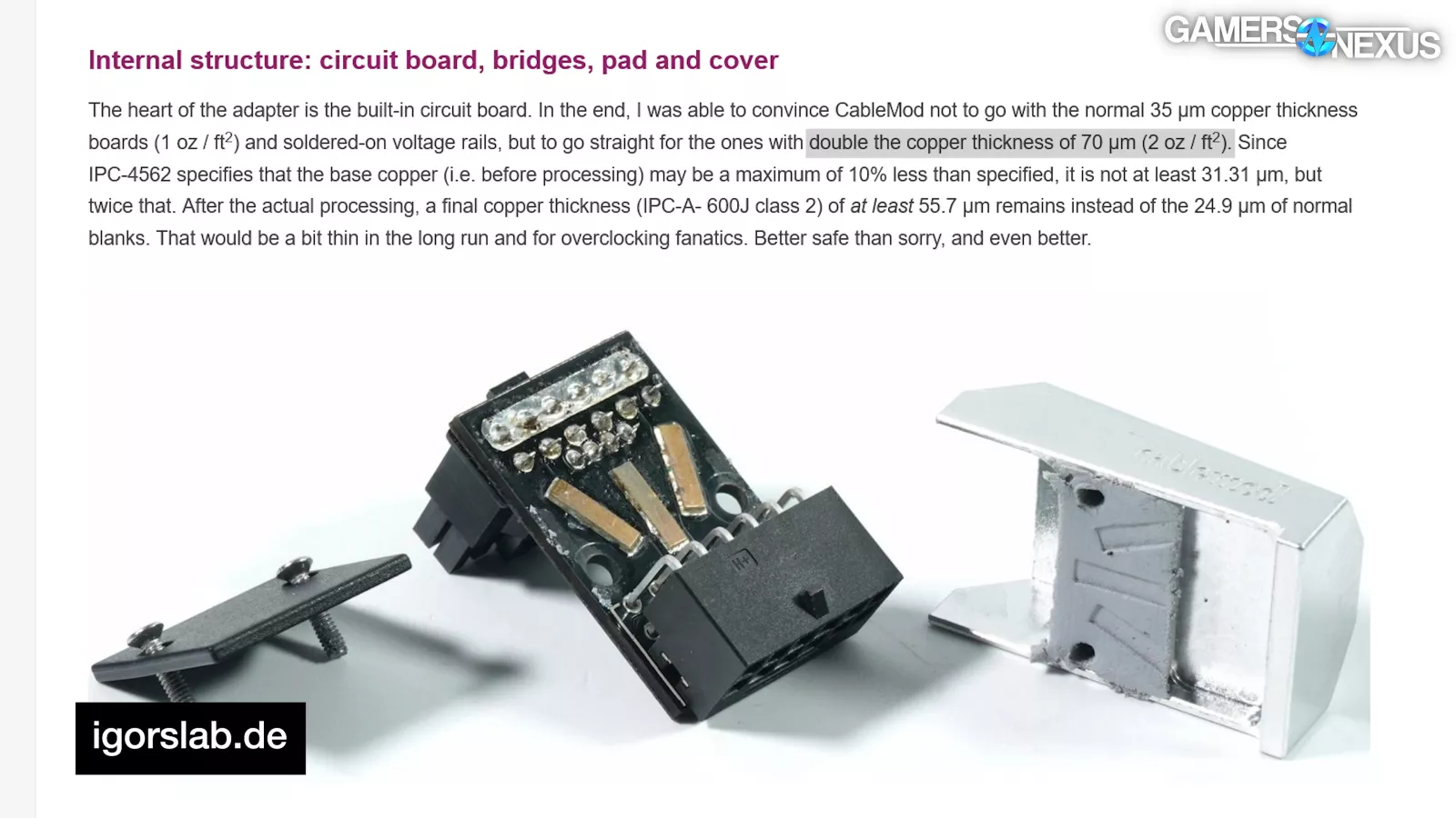
They had a specified copper thickness of 70μm within the PCB (reportedly double the usual), they had three massive copper bars soldered to the PCB as reinforcement for pairs of 12V traces, they had an aluminum housing mated to the PCB with a thermal pad for heatsinking, they used PCB rather than plastic as a cover plate for additional heat resistance, and they used the shorter sense pins that NVIDIA had been considering in the female connector.
Except that doesn’t appear to have been true.
As far as we can tell with our units, the 4 spring terminals and shorter sense pins didn't make it into production for these CableMod adapters.
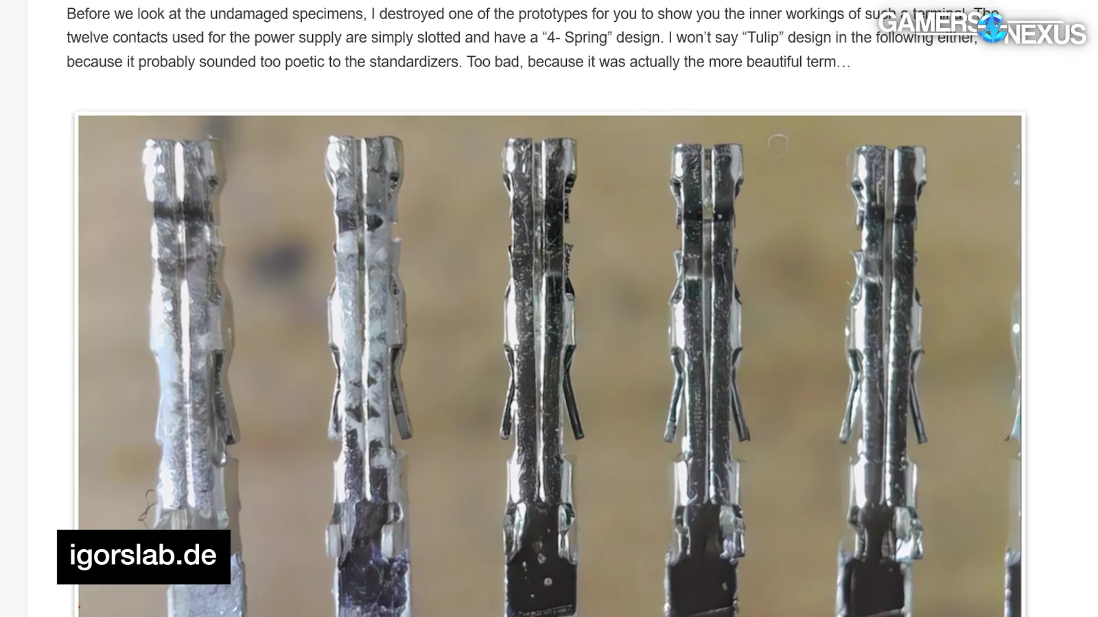
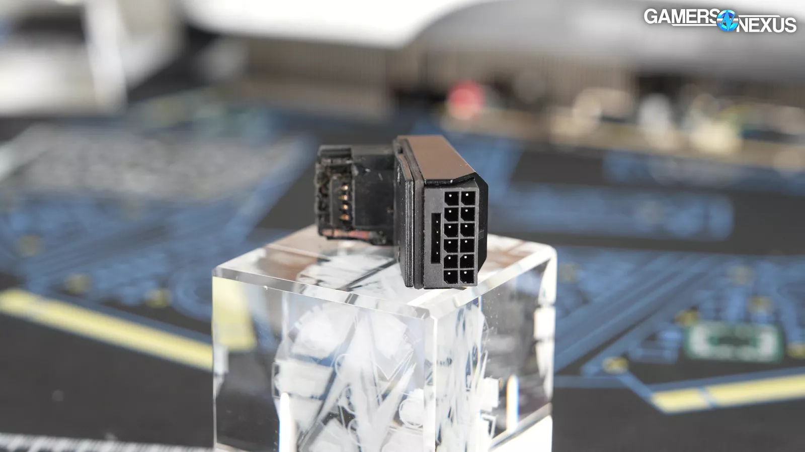
Igor showed detailed close up shots of the terminal pins in a prototype adapter, which clearly don't match the ones in our failed 1.0 adapters. The sense pins on the female connectors weren't any different from contemporary pre-revision connectors on GPUs.
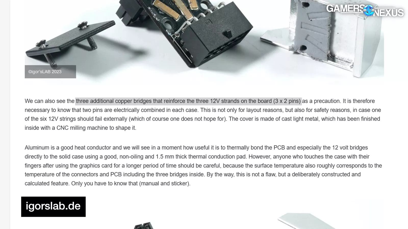
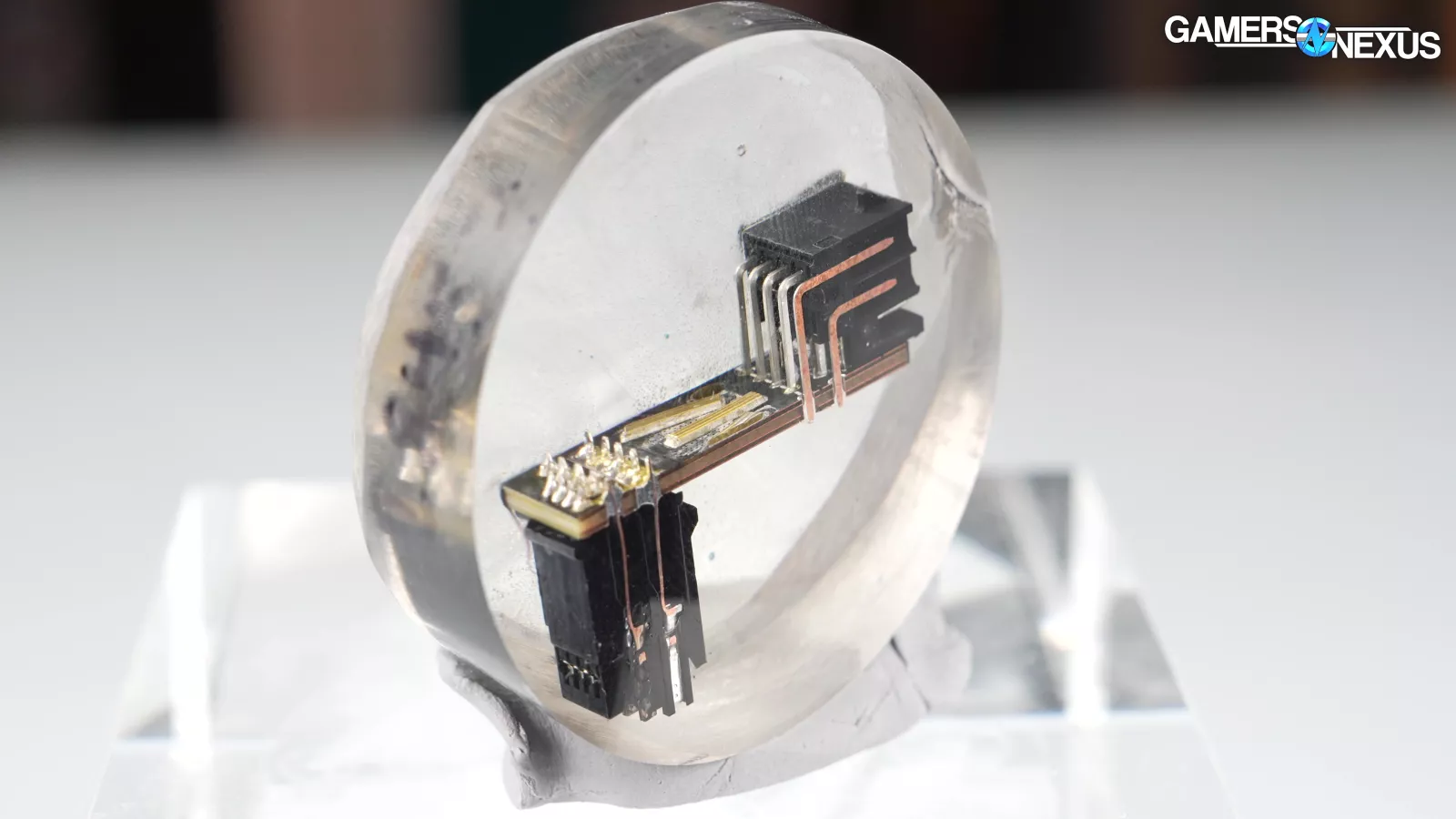
Finally, the claimed "three additional copper bridges that reinforce the three 12V strands on the board (3 x 2 pins)" where "two pins are electrically combined in each case" for "safety reasons, in case one of the six 12V strings should fail externally" are not actually connected like that, at least not in ours. In our CableMod 90-degree adapters, the two outer bridges are connected to all six ground pins and the inner one is connected to all six 12V pins. While at one point it may have been that way, it wasn’t in our production units.
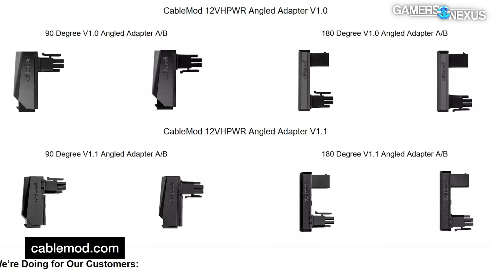
The 180 degree adapters are the same, but with twice as many bridges. We don't believe these factors were directly to blame for the failures, but it wasn't a good sign that the 1.0 retail adapters didn't match the exclusive first review of them by someone who was so close to their design and seemingly, at least in some way, consulting on it.
Two months later, on May 18th, NorthridgeFix posted a video called "4090 FE Connector melted with Cablemod Adapter installed. 40 series cards should be recalled." It was later established that part of this initial batch were eight damaged units sent by CableMod to NorthridgeFix as part of its RMA process. The shop has continued to receive damaged cards to this date.
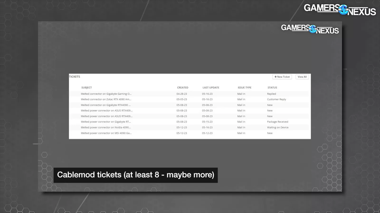
CableMod claimed that at this point, it had had eight reported failures out of more than 50,000 adapters sold (a .016% failure rate if that’s true), and that four of those were confirmed to be due to partial insertion.
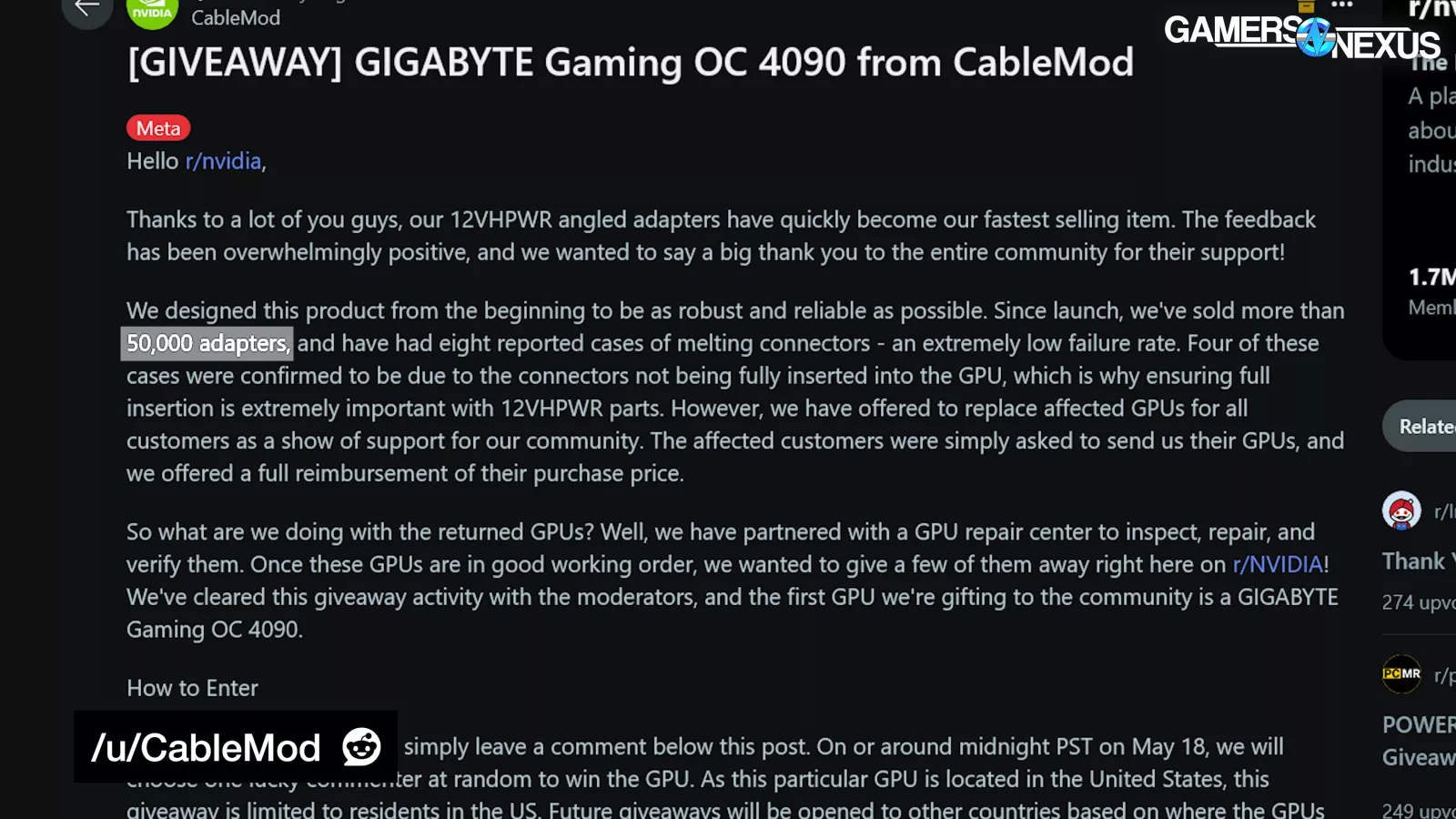
We now know that 50,000 number possibly included all 12VHPWR products sold by CableMod at that time, not just adapters, so the true failure rate of the adapters would have been higher. This was within two months of the product launch, and on adapters that were specifically designed to resist this exact issue.
Worse still, at least one of the adapters had definitely melted into place while fully seated, indicating a new problem -- and that problem would lead to CableMod’s recall of its faulty adapters.
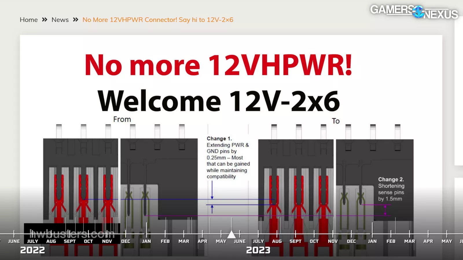
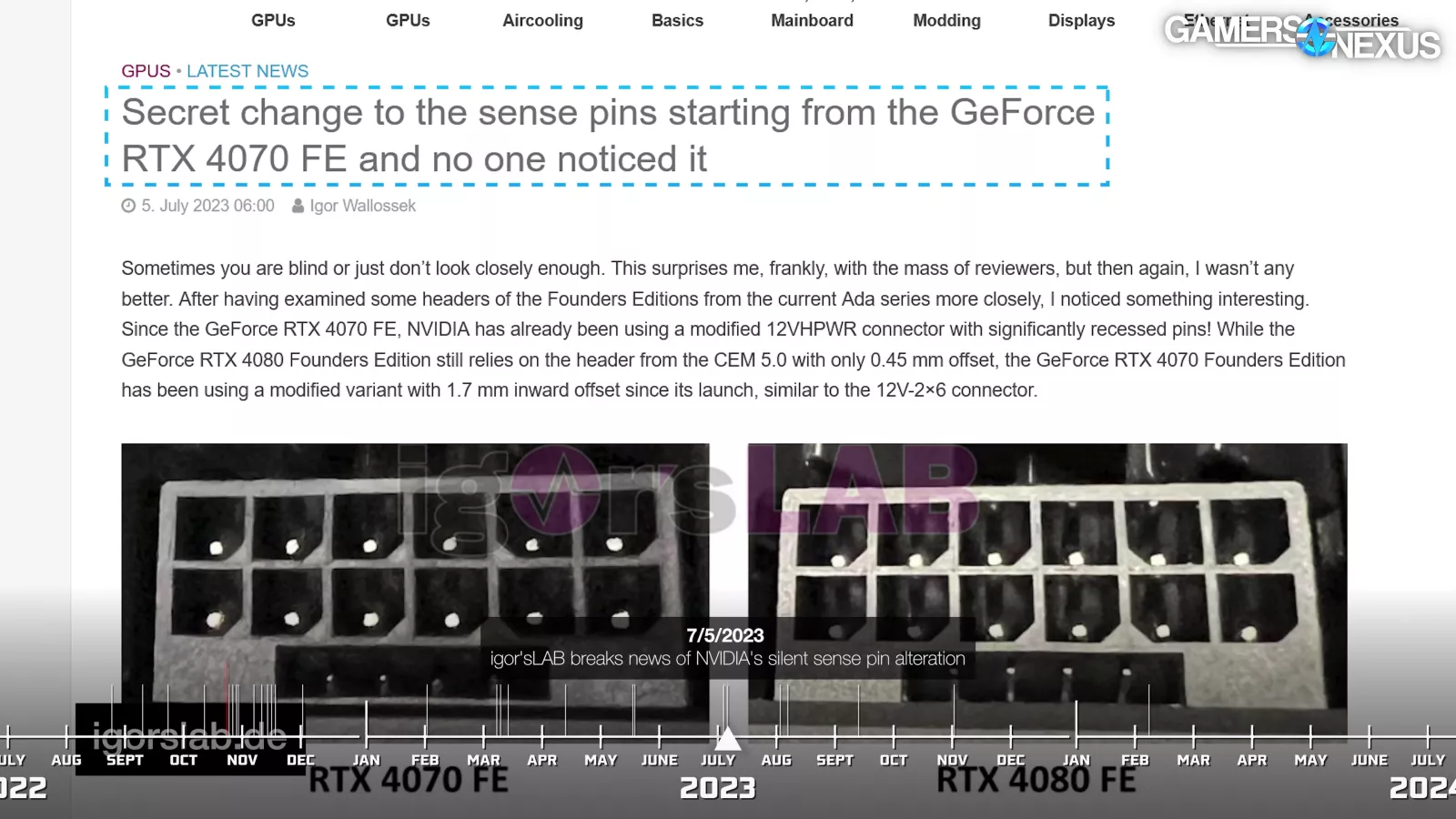
In July 2023, Hardware Busters revealed that the 12VHPWR connector would be replaced with the compatible-but-revised 12V-2x6 connector in the upcoming PCIe CEM 5.1. Igor then discovered that newer NVIDIA cards had silently rolled out an early variant of this connector as early as April of 2023.
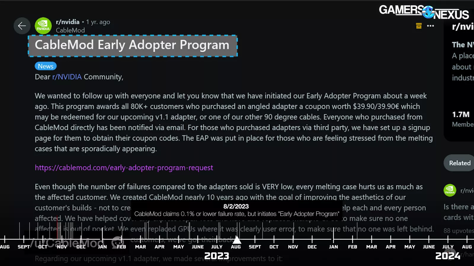
By August, CableMod was working on the "CableMod Early Adopter Program" to replace the original 1.0 adapters with an updated 1.1 version. It stressed that "the issues seen with our V1 adapters can't be pinned on NVIDIA and the new 12VHPWR standard directly," accepting the blame and responsibility for what was at this point a growing but "at most 0.1%" failure rate, according to the company.
The new 1.1 adapters incorporated these changes. First, they used the 12V-2x6 connector. Secondly, the connector was made to fit more tightly following a suggestion from JayzTwoCents. Third, the connectors were staked to the PCB to prevent wiggling. CableMod remained confident in its other non-PCB-based 12VHPWR products.
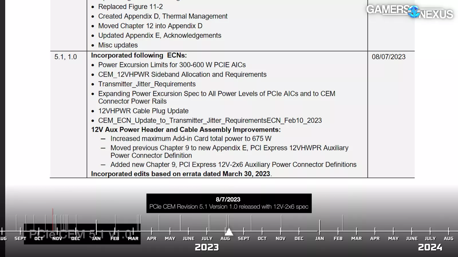

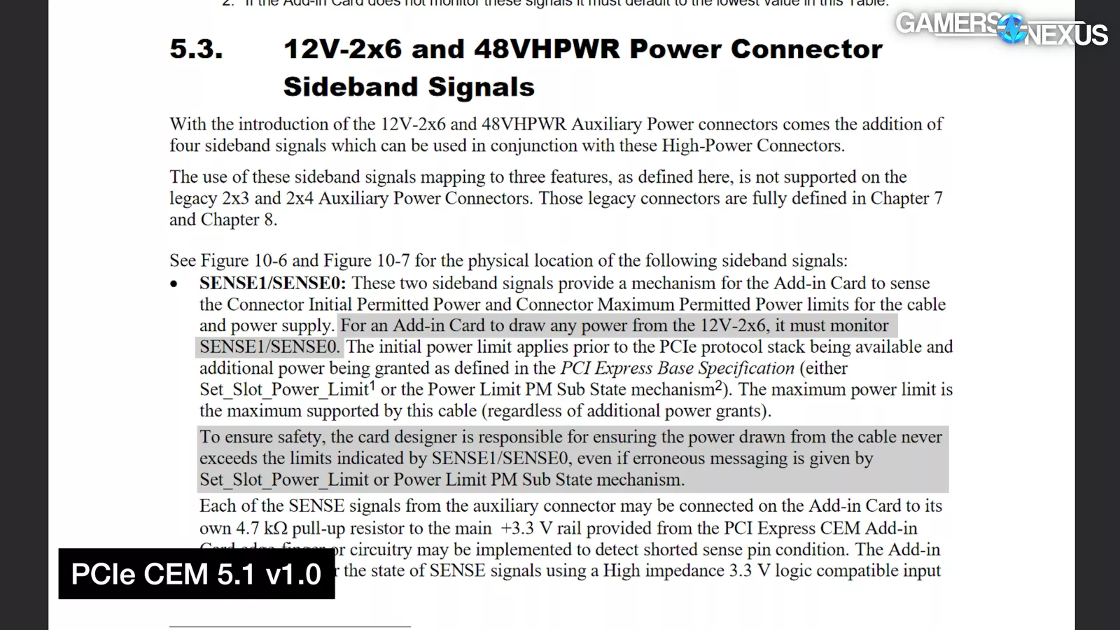
Finally, on August 7th 2023, the current PCIe CEM Revision 5.1 version 1.0 rolled out, incorporating a full year's worth of ECNs (Engineering Change Notices) that mostly revolve around the new 12V-2x6 connector, with the original 12VHPWR definition bumped down to an appendix. Both sense pins are marked as required and Add-In Card partners are required to monitor both in order to draw any power.
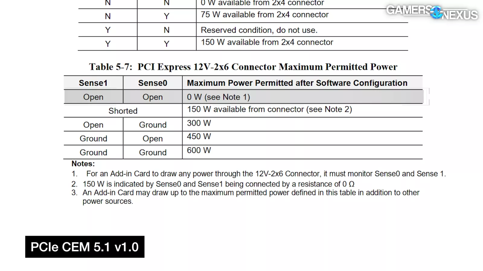
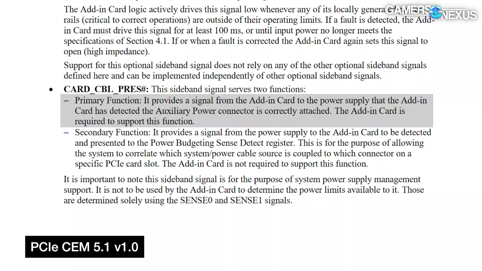
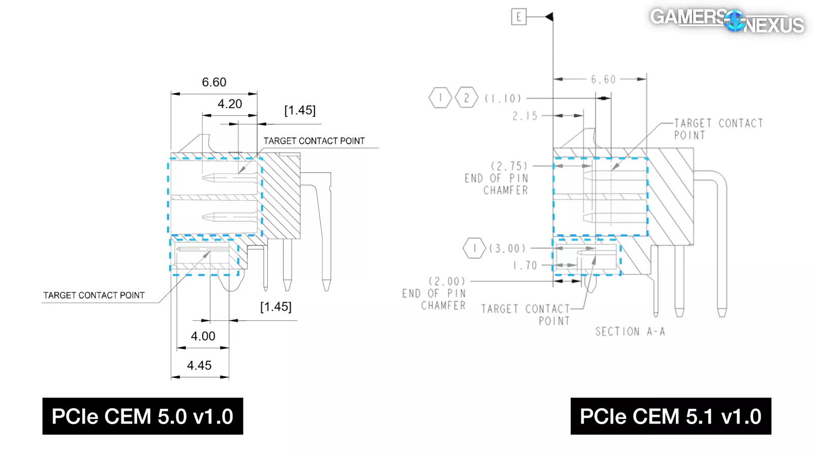
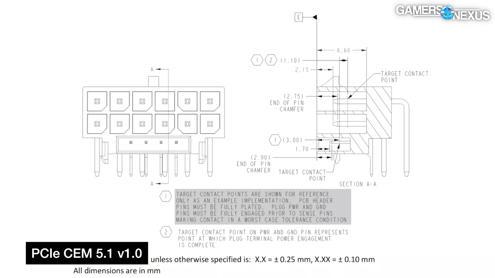
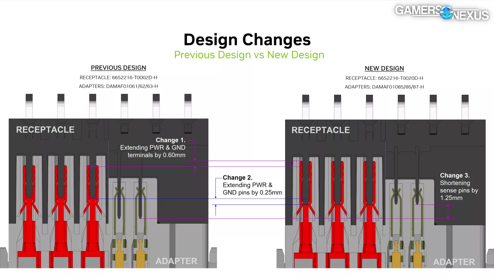
The Open/Open condition has changed from 150W to 0W, with 150W now signaled by shorting the two pins together. AICs (but not PSUs) are also required to support the primary function of the previously optional CARD_CBL_PRES signal to provide "a signal from the Add-in Card to the power supply that the Add-in Card has detected the Auxiliary Power connector is correctly attached." Power and ground pins are extended by 0.25mm and sideband pins shortened by 1.25mm. There are other numbers online cited for these mechanical changes, but these are the correct ones defined officially by the spec. Exact terminal length isn't part of the CEM ("plug pwr and gnd pins must be fully engaged prior to sense pins making contact in a worst case tolerance condition"), but we've seen NVIDIA documents showing that the terminals are lengthened by 0.6mm in its own adapters. Several tolerances are also tighter. All of these changes are intended to keep cards from drawing power without being fully plugged in or properly inserted.
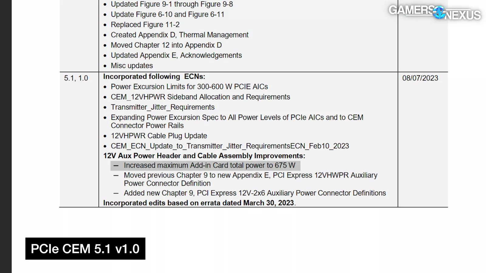
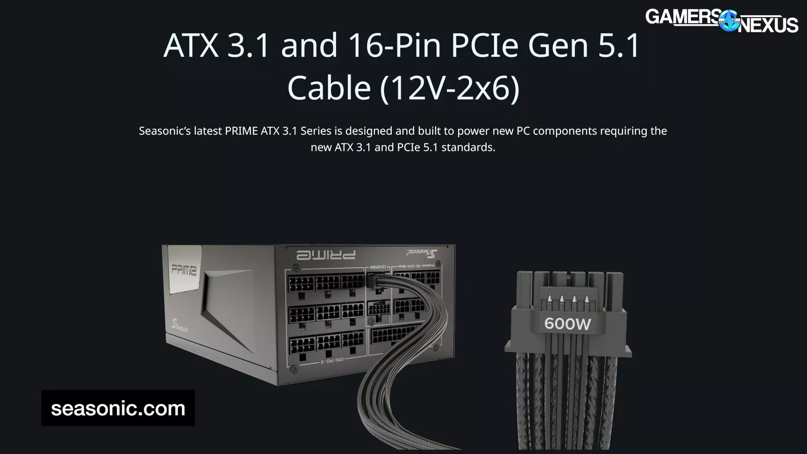
As a side note, the CEM "Increased maximum Add-in Card total power to 675 W", but that includes slot power. This is confusing for them to state in this way because the 12V-2x6 connector is rated to deliver 600W of additional power, just like the 12VHPWR cable, which has caused some confusion.
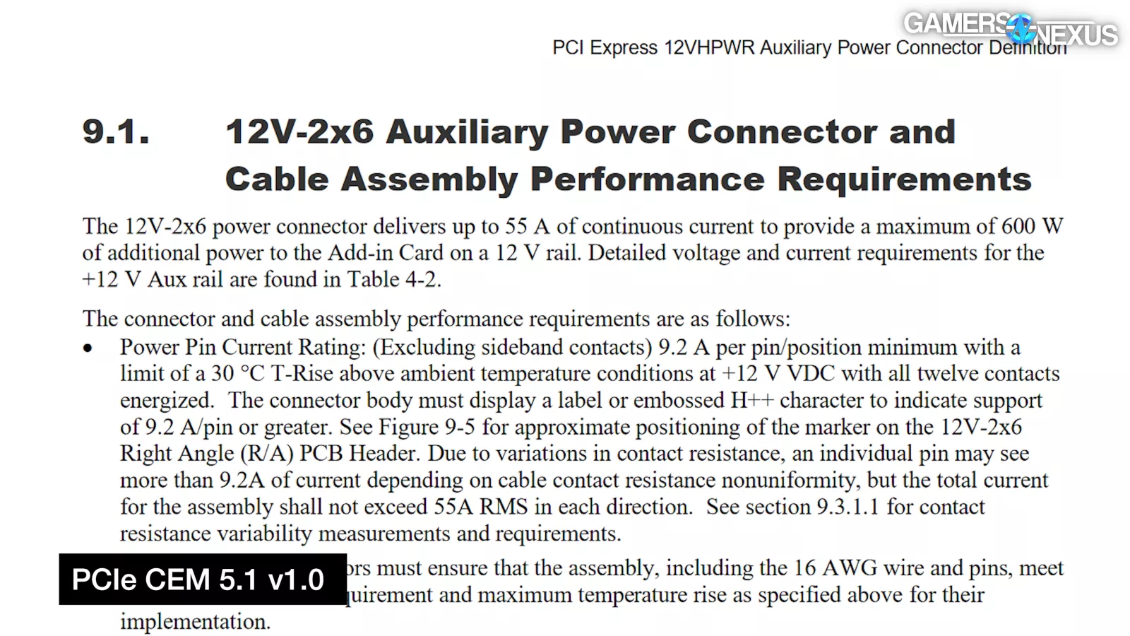
Here's what the spec says: "The 12V-2x6 power connector delivers up to 55 A of continuous current to provide a maximum of 600 W of additional power to the Add-in Card on a 12 V rail." So in other words, please stop saying 675W unless you’re also going to start talking about the slot.
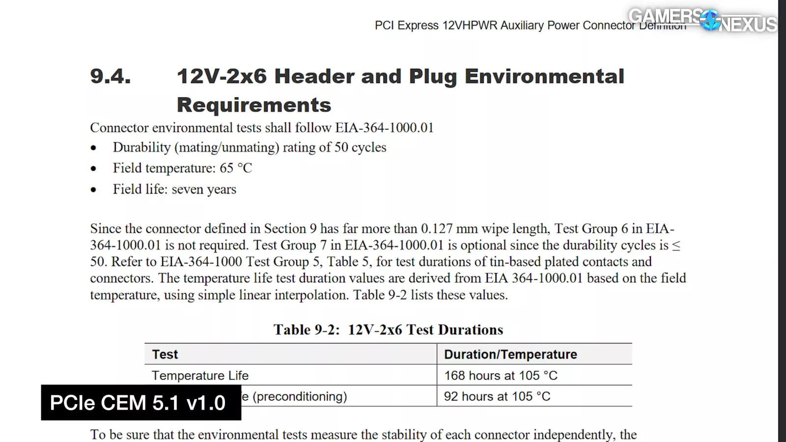
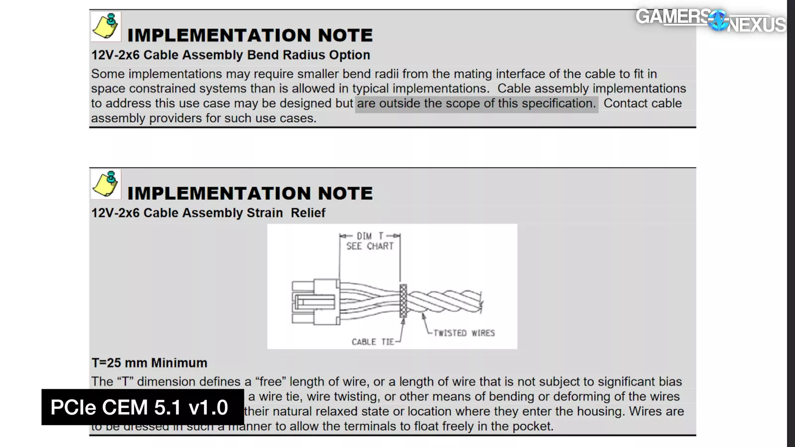
Extensive sections to the CEM were added to describe cable assembly best practices, warn that individual pins could see more than 9.2A, warn about low-level contact resistance and side-loading, and discuss environmental durability. At least 25mm of untwisted or bent wire past the plug is now required, and designs intended to get a smaller bend radius (like right angle cables) are "outside the scope of this specification."
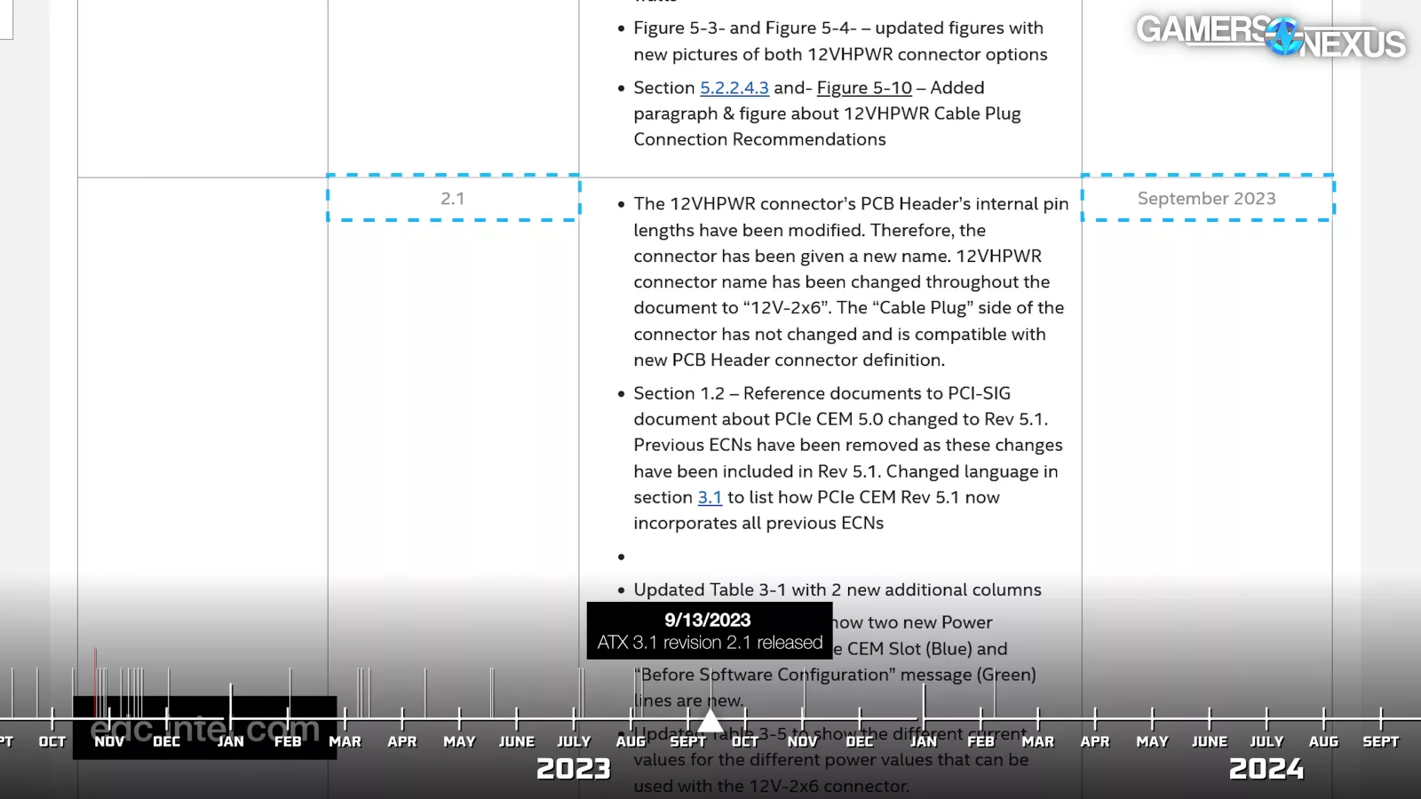
The ATX 3.1 revision 2.1 spec released shortly afterwards noted that "the 'Cable Plug' side of the connector has not changed and is compatible with new PCB Header connector definition." To this day, the newest male 12V-2x6 connector spec is basically the same as the original 12VHPWR one.
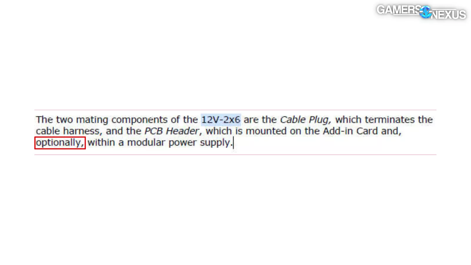
Even the newest revision isn't perfect. For example, as Aris pointed out to us, the spec says that for modular power supplies "an additional 12V-2x6 PCB Header connector will be required in the housing of the power supply," but it also says "the PCB Header [...] is mounted on the Add-in Card and, optionally, within a modular power supply,” furthering the contradictions of the spec documents.
With that in mind, let's revisit CableMod's proposed changes to v1.1 of the angled adapters. First, "CEM 5.1." CableMod said that "V1.1 adapters will include a CEM 5.1 female connector," but that wasn't the side of the adapters that melted, so that was unlikely to help.
Second, "Connector tightness." The connectors did need to be tighter, but connectors melting in place while fully seated hinted at a separate problem for CableMod.
Finally, "Connector wiggle." CableMod used plastic stakes to fasten down the male connector to the PCB, but the company outright said that this "didn't affect performance in our tests" and was done "for the sake of user experience."
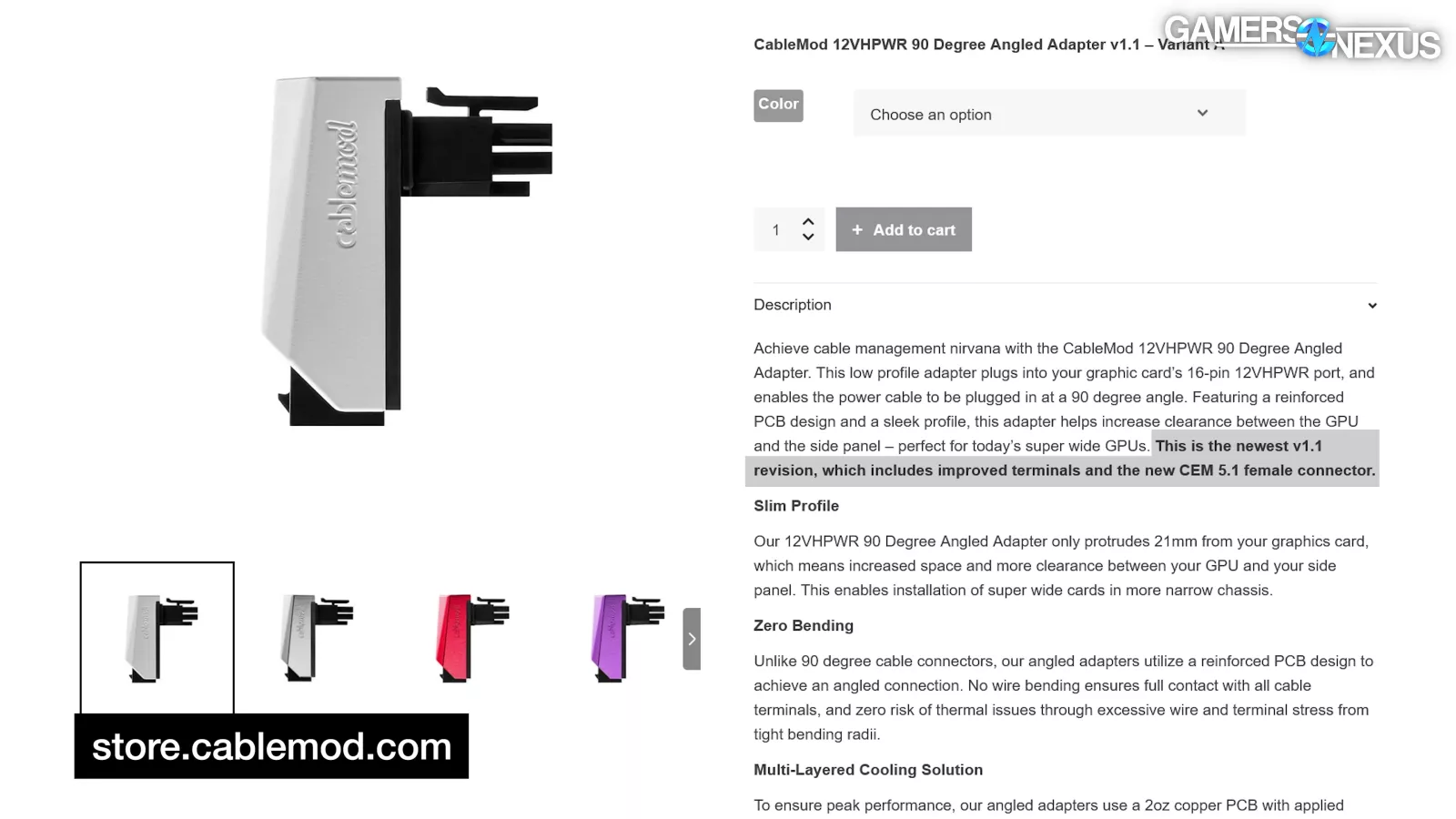
The product page for the 1.1 adapter also later claimed "improved terminals." The 1.1 adapter wasn't a fix, but that was the clear implication of the replacement program.
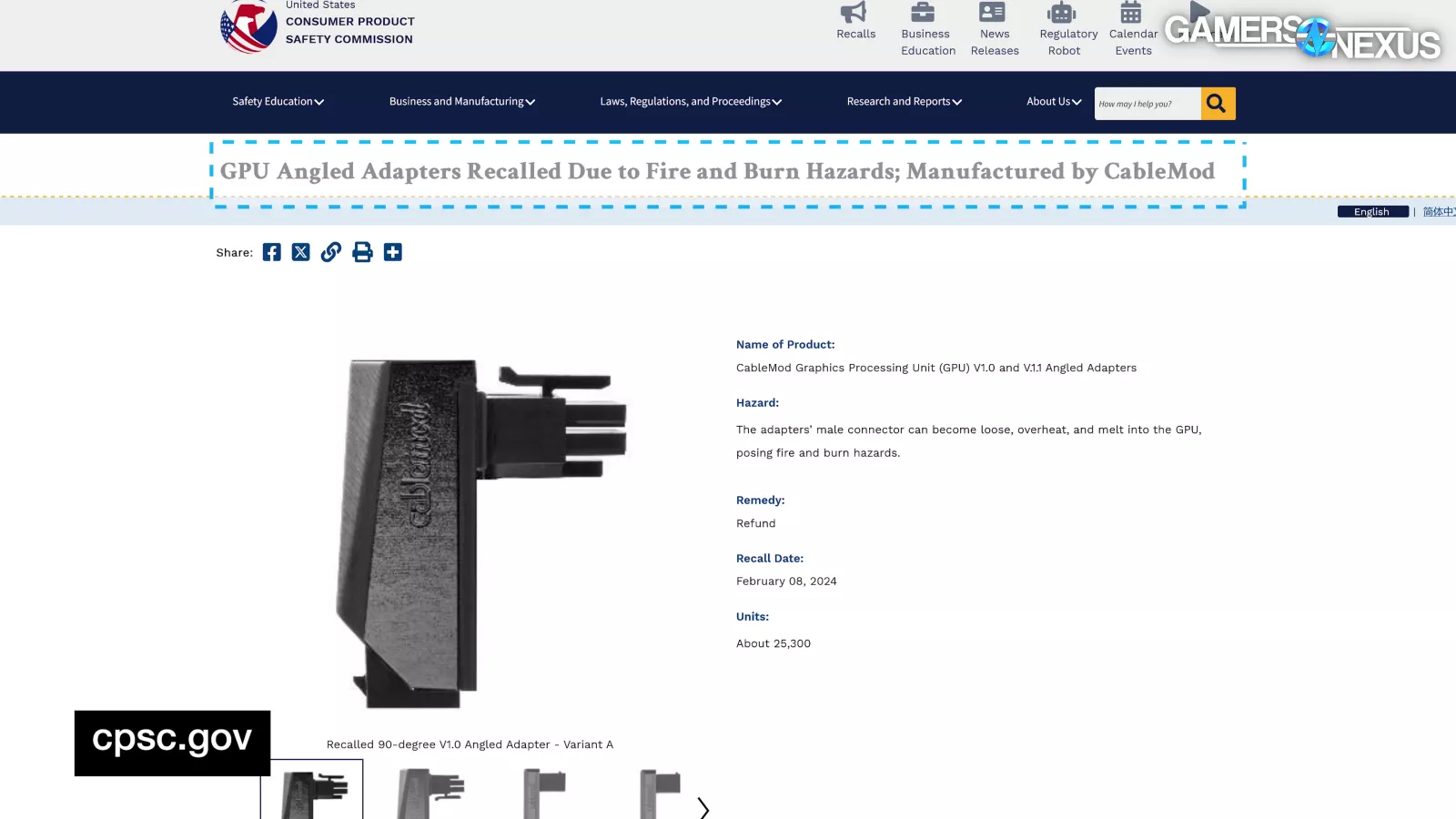
It didn't help. On February 8th 2024, CableMod threw in the towel with a voluntary recall for all angled adapters through the US CPSC government agency.
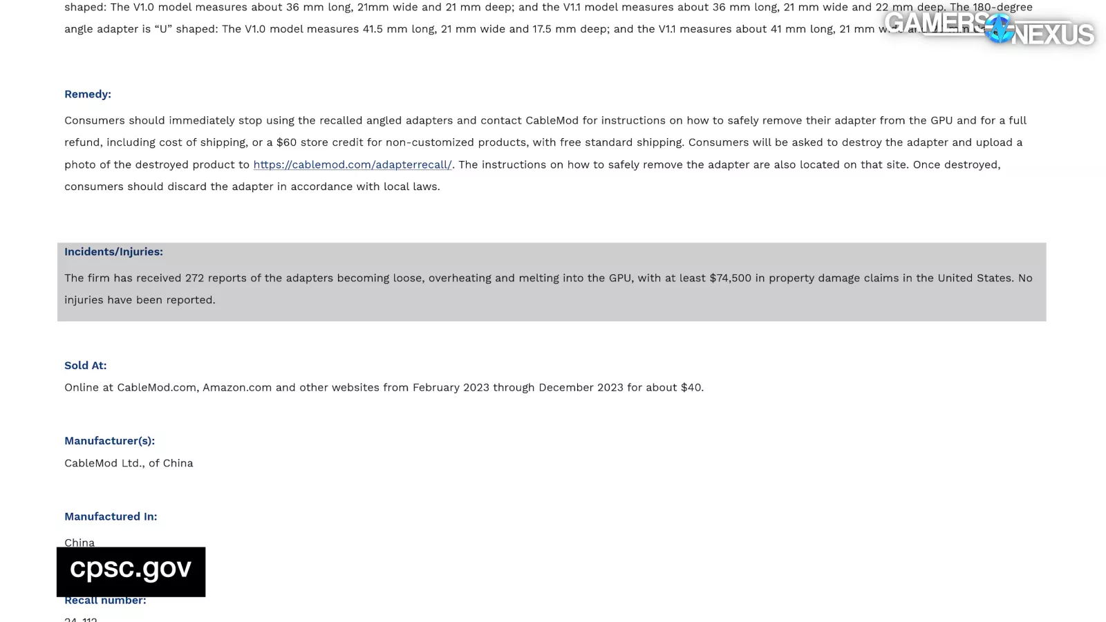
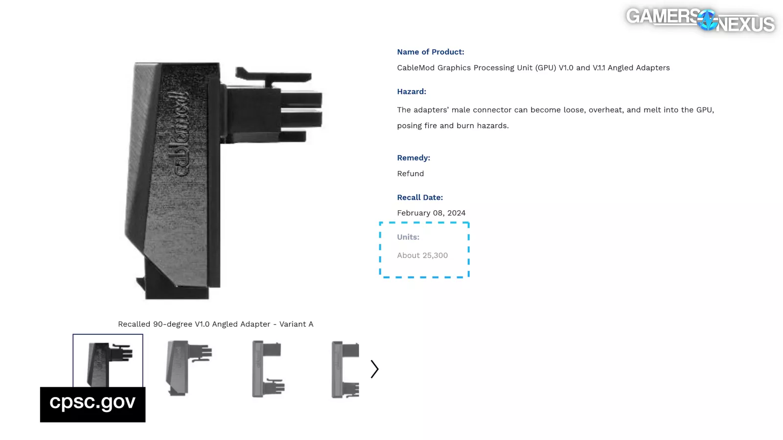
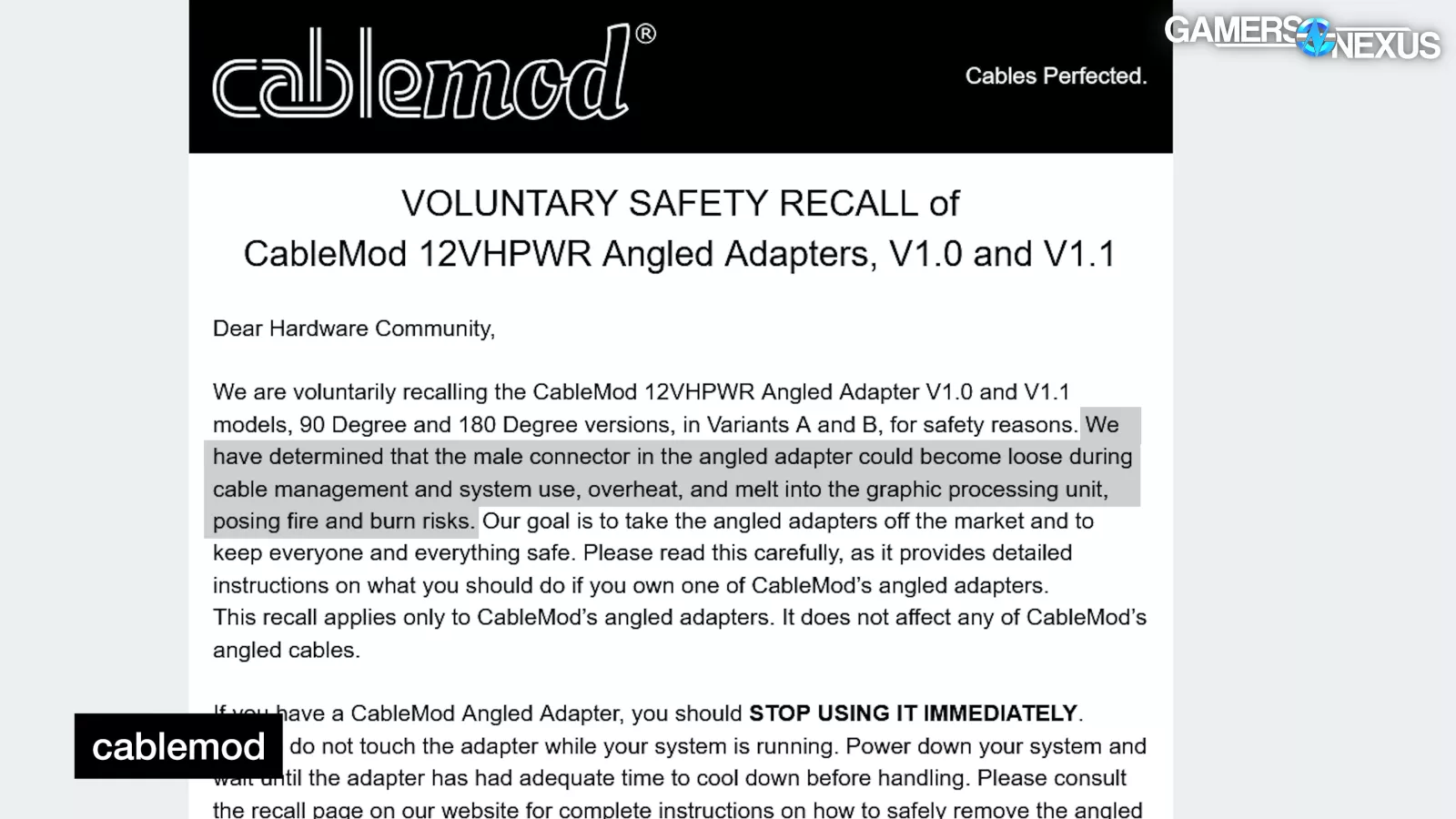
According to the CPSC notice, which is a government agency in the US for consumer safety, there were 272 reported failures out of approximately 25,300 affected units, a failure rate slightly over 1% in one year and an order of magnitude higher than it had been in August. The phrasing used by the CPSC was that CableMod had "determined that the male connector in the angled adapter could become loose during cable management and system use, overheat, and melt into the graphic processing unit, posing fire and burn risks."
As far as we understand, we don't believe CableMod ever conclusively identified a root cause for the failure of its specific adapters, but in the absence of a clear answer, it still deserves credit for the replacement and recall programs. That much is good, and most companies wouldn’t go that far. We also want to give CableMod credit for actively purchasing, fixing, or reimbursing customers for cards that were damaged as a result of use of their solutions. While this should be expected of any company, it’s rare.
The failure analysis lab we hired also could not come to a firm conclusion as to the specific common cause of failure of CableMod’s adapters. It did, however, have some key indicators for potential causes of failure for the ones that we sent in. As we stated in the beginning, the key indicators of failure included bad soldering work, choice of solder material, potential fractures in the pins as a result of the design, and general workmanship issues.
Conclusion

As we reach the conclusion here, a quick note that these kinds of deep-dives truly require community support. We have over 300 hours invested into this piece, with most of that being research and validation. To support our efforts, please visit store.gamersnexus.net and consider grabbing one of our PC building anti-static modmats with wiring diagrams, our soldering & project silicone mats that are excellent for not only high heat tasks like soldering, but also for model building, painting, and crafting projects, or our other items, like our 3D drink coaster packs that include common PC component theming to provide you with high-quality coasters that represent this enthusiast hobby. You can also throw us a few bucks per month on patreon.com/gamersnexus.
Thanks for your patience with these promotions as we continue to ramp our in-depth coverage the past few months for true deep-dives. Your support makes this possible. Back to the conclusion.
After all this, we don't really “like” 12VHPWR or 12V-2x6, but it's here to stay.
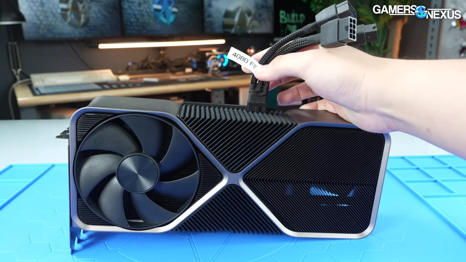
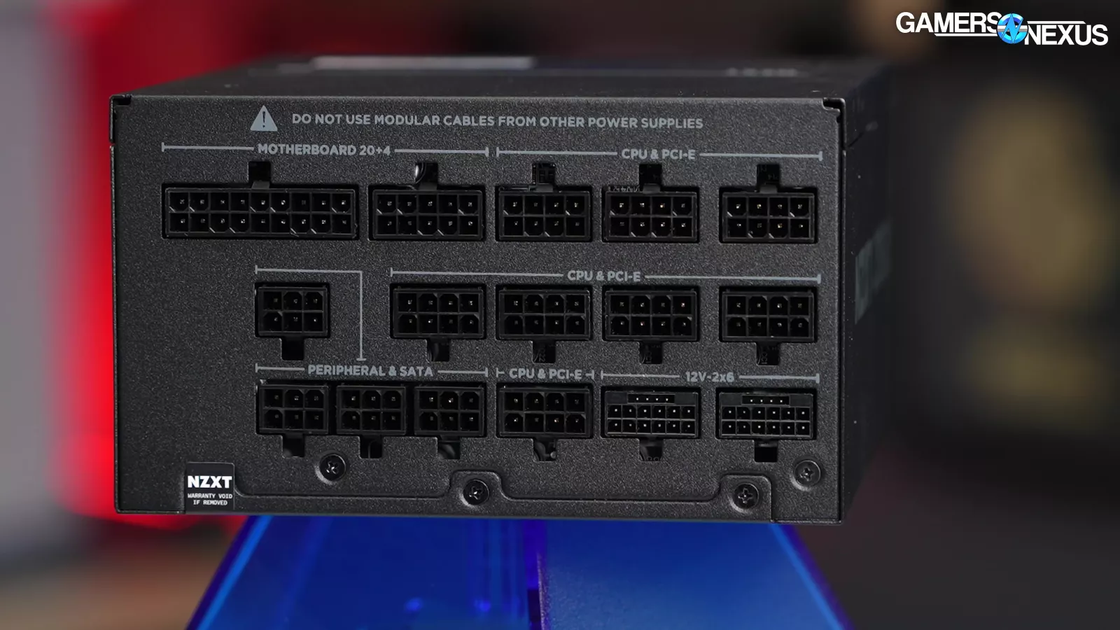
Right now, we recommend a native 12VHPWR/12V-2x6 cable, if for no other reason than it eliminates additional points of failure: simpler is better. Opinions may differ on this. For instance, Aris of Cybenetics thinks 2x8 pins on the power supply is the best. Here’s what he sent to us when we were talking about this: “The best way to reduce problems is to use 2x 8pin on the PSU’s modular board instead of a native 12V-2x6 since the former allow for more cable flexibility and are more tolerant to abuse in general. I advise PSU manufacturers to do this, but in some PSUs, due to a lack of space in the PCB, this can be an issue, so they are forced to use 12V-2x6 socket(s).”
We agree with der8auer that NVIDIA using 2x 12V-2x6 connections on high wattage cards would restore some of the redundancy and safety margin that the PCIe 8-pin connectors had developed. We wouldn’t want or expect them to try to fully utilize those connectors the way they do a single one though, as it will start approaching US 15A breaker limits for the typical household.
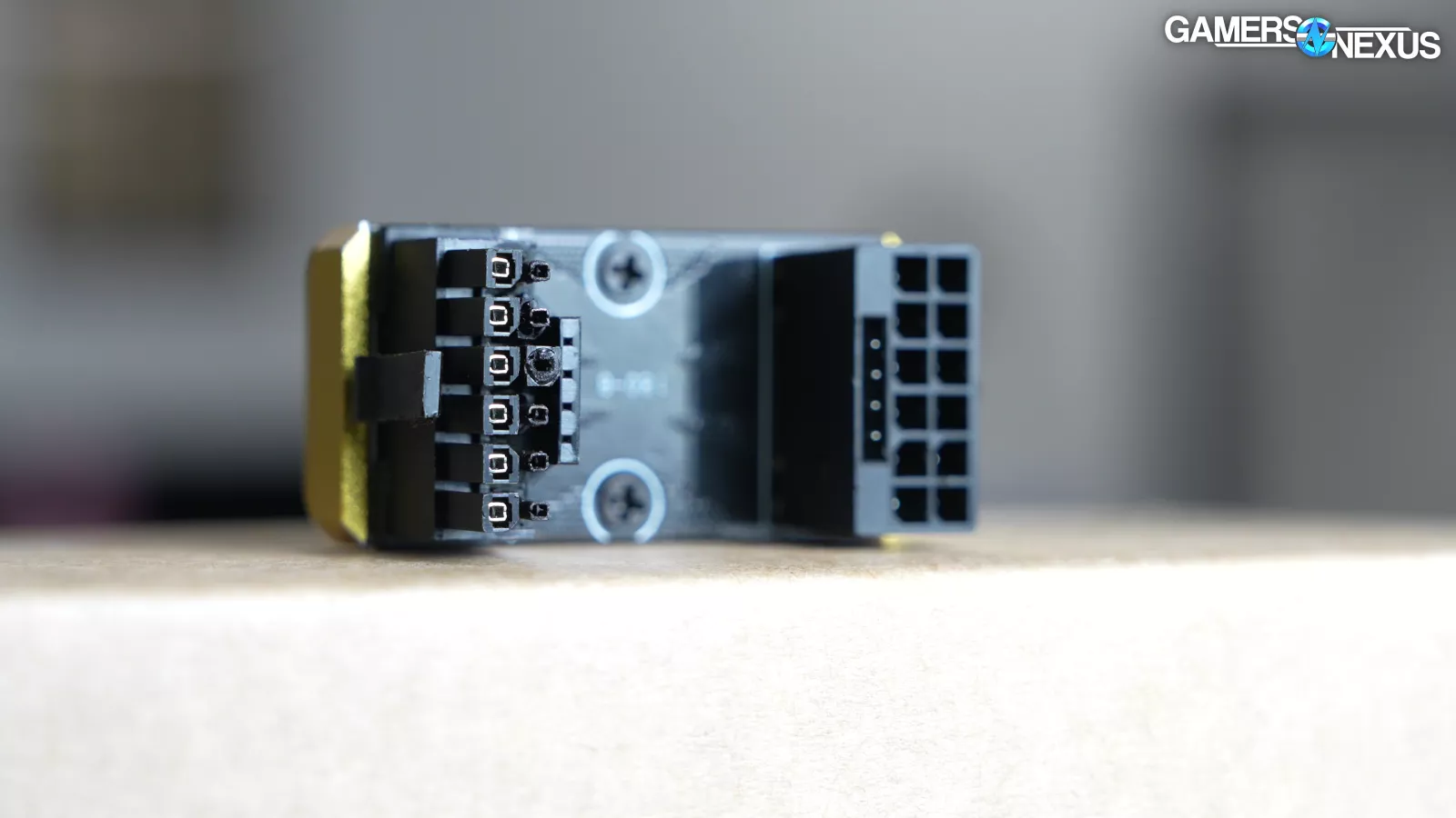
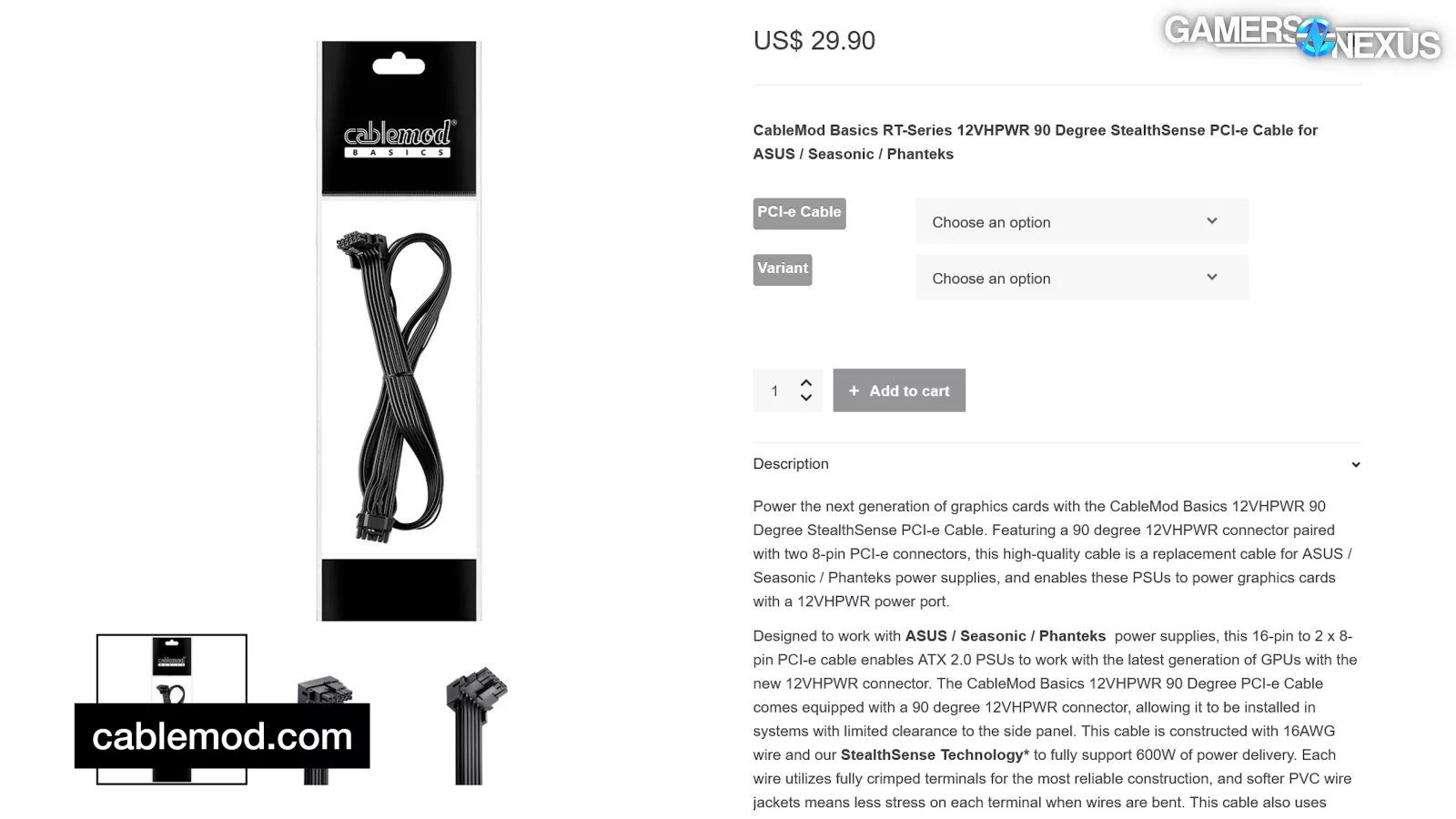
As for adapters, adapters fall outside the ATX and PCIe CEM specs. If you're using an ATX 3.0 PSU with 12VHPWR or 12V-2x6 but it doesn't have that plug on the PSU side specifically, it's using an adapter by this definition. There's no simple way to connect the sense pins with an adapter; for example, Corsair runs 12VHPWR connections out of two 8-pin connections on the PSU side with one sense pin grounded to each, which means that if only one 8-pin is plugged in, the GPU will be signaled that either 300W or 450W is available arbitrarily, depending on which one is plugged in.
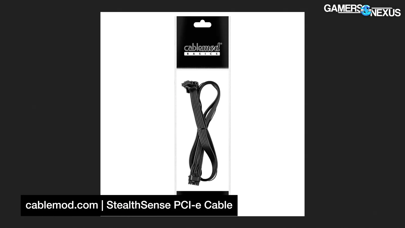
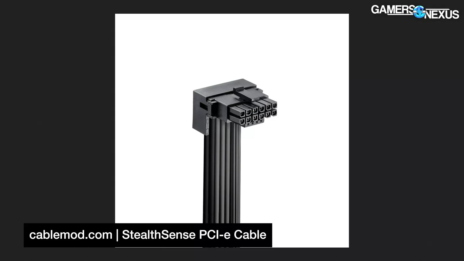
Some adapter cables don't connect the sense pins to the PSU at all, like CableMod Stealthsense. On paper, the most "correct" adapters are the dongles that ship with NVIDIA GPUs which intelligently ground the sense pins based on how many connections are detected. Obviously that didn't prevent them from melting to start with, but it is important to remember that those failures, when they happened, were much different from CableMod's. We’d also recommend continuing to always avoid sharp angles or pulling tightly on cables in general, but 12VHPWR and 12V-2x6 cables in particular. This has been a known issue since before day one. If at all possible, follow bend radius guidelines from the PSU or cable manufacturer.
If you're using a male-male double ended 12V-2x6 cable with your PSU, strictly speaking, the cable should have at least two visible sideband connections that run all the way from the PSU to the card. Since the CARD_CBL_PRES signal is now supported on the GPU side, up to three wires may be used. If a native 12VHPWR PSU meets spec, it handles sideband signals internally.
PSUs don't always set those signals properly, though. As Aris from Cybenetics told us, "nobody follows Intel’s recommendations, and you can see 600W [shown as available with] 12V-2x6 on a 650W PSU! This is ridiculous and I am so tired of writing this down on our Cybenetics reports." These recommendations aren't in the ATX spec itself, but they are in the Intel-published Desktop Platforms Power Supply Test Plan.
Aris continued: "Many ATX v3.x PSUs ignore this Intel guideline and have a 600W setting on their 12V-2x6 connectors. Remember this setting should NOT be applied on the cable, but within the PSU."
Some third-party double-ended cables like CableMod Stealthsense ignore the PSU and "signals to the GPU that a full 600W is available to be used." This isn't ideal, but it's intended to avoid another common issue which manifests with a black screen and GPU fans running at max speed. Many of you reported having this problem in our survey that we ran. This is likely due to sense pins losing connection, whether that's from "fragile sense pins that can easily be dislodged" as CableMod suggests, or just vibration and thermal expansion. Since 12V-2x6 intentionally makes the sideband connections more tenuous, we expect this to become more common. If you experience this problem, it can be worked around by using a different cable.
One last recommendation we have here is to make sure the cable is fully seated. That still matters a lot. It might be one of the things that matters the most after choosing a cable that's not designed with some kind of fault in it, like the CableMod adapters were, because there isn’t a ton of headroom. Also, be mindful that pulling one side can loosen contacts.
And finally, the RTX 5090 (beware of scalped prices) gets a mention: At the time of this writing, the card isn’t yet out, and at the time we’re publishing this, there are conflicting rumors about the device. In the past, leakers have gotten the power specs wildly wrong about GPUs, so we’re unable to make any firm recommendations or commentary until the true specs are known. Currently, the leak indicates a 600W TDP on the RTX 5090 (beware of scalped prices); however, last time leakers suggested 800W and 600W GPUs in consumer, it turned out that these were simply the recommended design guide for the cooling solution, not the actual power consumption. For sake of discussion, if we momentarily assume 600W is truly the “TDP” of this card, then our concern would be regarding running a single 12V-2x6 connector for the card. The cable itself is not rated for 675W, as we said earlier, and this is a common misconception. Between the cable, its limited overhead, and the PCIe slot, we would feel uncomfortable with how close these limits are to the power consumption. Der8auer felt the same way when we discussed it with him. If NVIDIA goes with two connectors, they’d have plenty of headroom. For now though, until those specs are finalized, there’s no point discussing this further. We’ll comment on it once we know more.